Learn Arduino?

VK3ZYZ

Moderator
Staff member
Yes, I2C is very handy. Now I only use I2C displays on the Arduino. And for bigger stuff on the ESP32, the SPI interface.
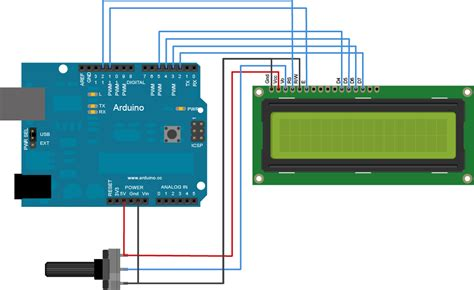
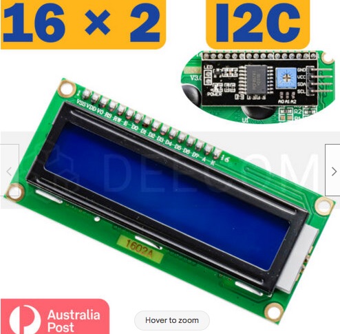
For example, the LCDs have 14 pins, or 16 if you include the back light.
There are 2 power pins, 1 contrast, 3 control pins and either 4 or 8 data pins depending on the mode of operation of the LCD. 8 data pins will be faster but for most times, speed is not an issue for character LCDs.
This is an image I found to show the LCD in the 4 bit mode. D0 to D3 are not used. So 6 Arduino port pins are in use.
In fact, there is another pin, the Read/Write pin that is usually connected to 0V, but can be driven with another port pin if you want to read the LCD RAM. But this is not often done.

1658444744125.png


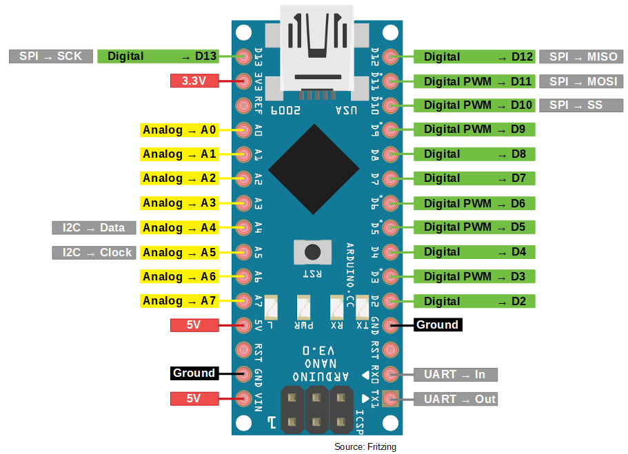
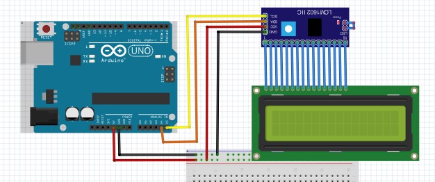
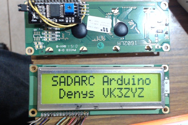
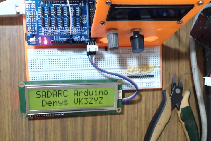
If you use an I2C interface to drive the LCD, the LCD connects to the I2C board and only 4 wires go to the Arduino. 2 of these are the power, so just 2 port pins are needed.
1658445008123.png


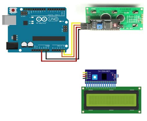
And, these 2 pins, the SDA and SCL (data and clock) pins can be shared with other I2C devices that have a different address.
I2C is very handy indeed.
 
Last edited:

VK3ZYZ

Moderator
Staff member
Here are the layouts for the above lessons.
Blink is just the Arduino, nothing else is required.

BlinkPot and BlinkPot3 have a 10K pot connected as follows....
BlinkPot.jpg

(The pot value does not really matter. try whatever you have on hand.)
It is a good idea to link the +5V and GND from the Arduino to the breadboard rails along the side as shown. And most breadboards have a red line to indicate +V and a black one for GND.
On the breadboard itself, I tend to use some single core telecom cable for the links and cut them to size for neatness. If you can get yourself a short length of 50 pair cable, it has a great variety of colours.

BlinkPot2 has 2 pots...

BlinkPot2.jpg


And PWMPot just uses 1. But now, an external LED is connected to pin 9.
PWMPot.jpg

Notice that on the Arduino board, some pins have a tilde ( ~ ) printed near them. That indicates the pin supports the analogWrite command, that is, PWM output.
 

BillC

Active member
Thanks Denys for an interesting session yesterday morning,I am sure we are catching on a bit more.The syntax protcols require a bit of study. Thanks , Cheers.
 

VK3ZYZ

Moderator
Staff member
Next lesson we will try to get a display going.
I2CLCD.jpg

This looks like it. This has an I2C adapter board to make driving easy. Just 2 wires (plus 5V and Gnd).

Download this zip file and in Arduino. goto Sketch - Include Library - Add zip library... to install it.

Or you can unzip it into arduino/libraries folder before you start Arduino up.

Then, connect your LCD up and load the SADARC_LCD_DEMO to see if it works.
Arduino A5 to I2C_LCD_board SCL.
Arduino A4 to I2C_LCD_board SDA.
Arduino 5V to I2C_LCD_board Vcc.
Arduino gnd to I2C_LCD_board gnd.
Arduino_I2CLCD.jpg


You will need to adjust the trim pot first time for correct contrast.
Also, it is possible the I2C address is different than in the example file and that can be checked. In a later post ;)
 

Attachments

Last edited:

VK3ZYZ

Moderator
Staff member
96mm_LCD.jpg
96mm_LCD2.jpg

For the first few club members who are interested, I have some large I2C LCDs that I've put together from recycled displays.
These are 2x16 char, about 96mm long display area, and have the I2C board attached. You can have one for a measly $5.00 (no steak knives are included). First in first serve.
I hope to get some smaller ones going too. Still 2x16 char, just about 60mm display size.
Note! -These do not fit my 3D printed frame.
Give me a call/email.
 
Last edited:

VK3ZYZ

Moderator
Staff member
Here is an example of an Arduino pressed into service.
I have made an adapter board that fits an MCP23017 into a 6522 socket as I have quite a few I/O boards that were used in industrial control.
Photo on 9-8-22 at 7.43 pm.jpg

Here it is fitted to a DC16-OUT board.
These MCP23017 chips are I2C 16 bit port expanders, so if you need an extra 16 I/O pins, they prove to be very handy.
My board has an OOPS I made. The classic one! The +5 and gnd on the SMT chip are swapped :(
Hence the wire links.

This board has 16 FETs so it can quite well drive 4 x 5 wire stepper motors.
Here is a movie showing 1 motor, and some sample code.
 

Attachments

VK3YNV

Administrator
Staff member
Notes and links as discussed at Saturday's Arduino Course.

Digital and Analog Input and Output Summary (PDF Attached)
Arduino Nano pinout

Arduino-Nano-Pinout-1.png


Home work problem.

Read an analog input ( from a pot or a sensor ) and turn on a digital output when analog input is greater that some number.

// Solution to the homework problem.


Code:
// This is for a raspberry pi pico W

#define pot  A0   // change to suit your board
#define rly  D0   //

void setup() {
  Serial.begin(115200);
  pinMode ( rly, OUTPUT);
  digitalWrite(rly,HIGH);
  delay(1000);
  digitalWrite(rly,LOW);
 
}

void loop () {
    int val;
    val = analogRead(pot);
    Serial.println(val);
    if (val>200) {
      digitalWrite(rly, HIGH);
    }
    else {
      digitalWrite(rly,LOW);
    }
}
Arduino programming reference. https://www.arduino.cc/reference/en/
 

Attachments

Last edited:

VK3ZYZ

Moderator
Staff member
I hope you have tried the exercises in posts 42-43 above.
Here is another that builds on those.
PotFetMotor.jpg

In this case, we are going to drive a motor instead of an LED.
This requires a few extra parts. The first, of course, is a suitable motor. And, as an Arduino output cannot supply sufficient current, a power transistor or FET is used. Note, that this will invert the sense of the signal so the FET output will go LOW when the gate is HIGH.
It is good practice to add a pull down resistor on the FET gate to hols it off while the Arduino is being programmed and starting up.
In a similar way, the resistor added between the pot wiper and the Arduino A0 input is just a protection in case the A0 is driven as an output.
Also, there is a reverse diode across the motor to clamp the back EMF generated to help keep the high voltage spikes from causing problems. As well as that, it does give smoother motor operation as the back EMF generated tends to keep the motor turning.
An external power supply is used to drive the motor, and this can be anything that suits your motor.

I will be interested to see if anyone has a go at coding this.
I'll try to dig up motors and batteries for you to use if you have none of your own.
See you at the Sat. 1st October SADARC meeting.
 
Last edited:

VK3ZYZ

Moderator
Staff member
This Youtube video looks pretty good so far as a basic introduction to the Arduino.( I am still watching it.)
It is a bit long winded but is assuming no knowledge it seems.
 

VK3ZYZ

Moderator
Staff member
For those of you who received an L298N board at today's Arduino class, here is a link to help you use it to drive a couple of DC motors.
1664605147398.png

I would not use a small 9V battery as shown in some examples. Those are too small capacity and relatively expensive to boot.
If you want to use a 9V battery, look into a 6 cell AA (or bigger cells) pack. Or just a mains plug pack. The voltage you select will depend on the motors.

The L298N can max out at 46V and a total of 4Amps. But do not run it to those extremes.

Here is a link to install the "official" L298N library.

Instead of a couple of DC motors, this chip can drive a 4 wire stepper motor..
For an old chip, they are still pretty popular.

Also, here is the device data sheet.
 

Attachments

Last edited:

VK3ZYZ

Moderator
Staff member
Here is a video on using various H bridge boars to DC drive motors, from toy size to large motors.
 

VK3ZYZ

Moderator
Staff member
If you are happy with the motor driving, next time we may have a play with LED displays. I will supply parts for a 4 digit version.
At the moment, I do not remember if they are common Anode or cathode versions.
Hve a look at another video from the DroneBot Workshop Youtube channel.
 

VK3ZYZ

Moderator
Staff member
I have a stack of TSB5882 4x7seg LED displays so all who attend the next class will get one to play with.
Following on from the the above video, install the SevSeg library so you can be ready to try these out.
SADARC-SevSEg_Meter.jpg

Here is a quick setup to read a pot and show it on the LED display.

I have modified the pin layout of the digits and segments to line up with the TSB5882 just to make it easier to wire up...

// pins in order to suit the TSB5882 display
// digits 1, 2, 3, 4 (staring from the left)
byte digitPins[] = {11,10, 8, 4};
// segment a, b, c, d, e, f, g, dp
byte segmentPins[] = {13, 7, 9,12, 5, 6, 2, 3};


1666140833876.png

EDIT: I think with low value resistors for the segments, and no buffers on the digit drive pins, it is possible to overload the Arduino so 470R even may be a bit low for continuous use.

The code is below.
 

Attachments

Last edited:

VK3ZYZ

Moderator
Staff member
My Arduino of choice is the Nano. And here is a handy add-on board that extends the pins out to terminal strips.
Nano Terminal Board.jpg

There were some on order and they were out of stock, but they arrived today.
 
Top