Learn Arduino?

VK3ZYZ

Moderator
Staff member
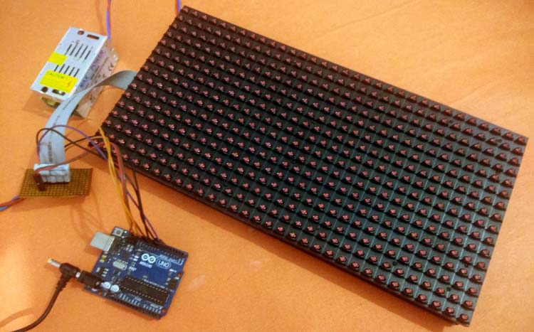
How about we play with a large LED display? Like this 32x16 matrix?
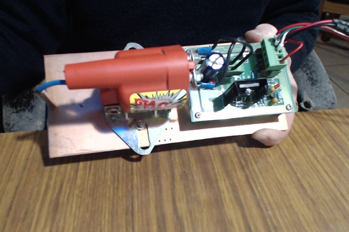
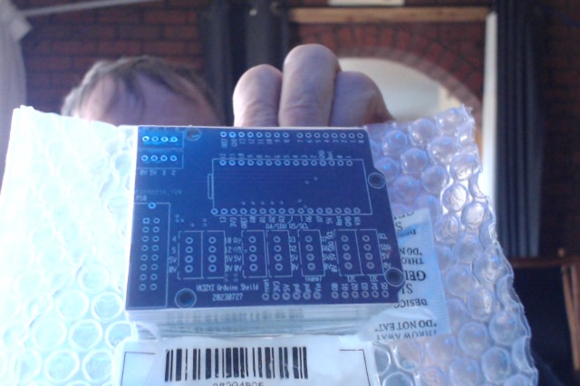
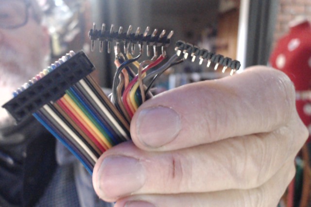
Here is a picture pinched from on line.

Digital-Notice-Board-using-P10-LED-Matrix-Display-and-Arduino.jpg


ConnectedToArduino.jpg


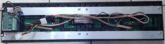
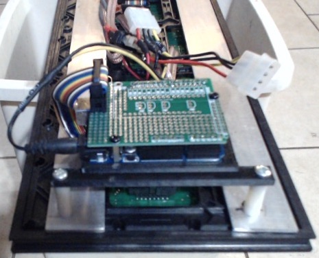
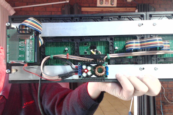
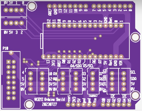
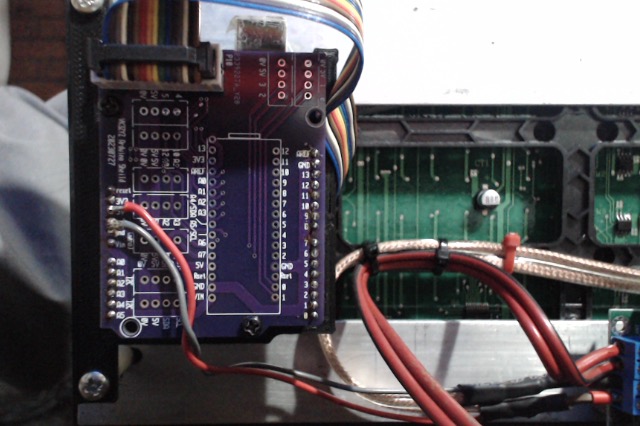
The parts on the back identified ...
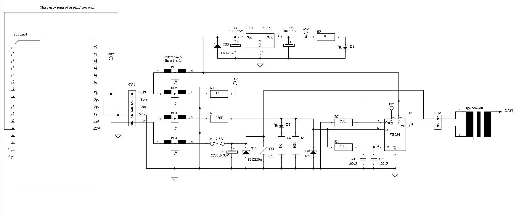
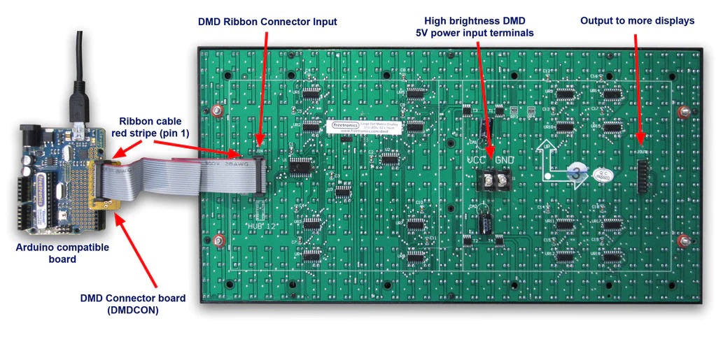
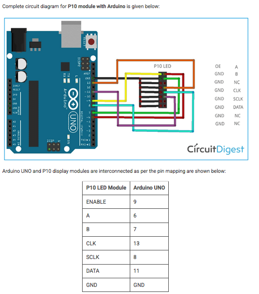
P10_Parts.jpg
and a circuit...

P10_Circuit.gif
Arduino_P10_connections.png


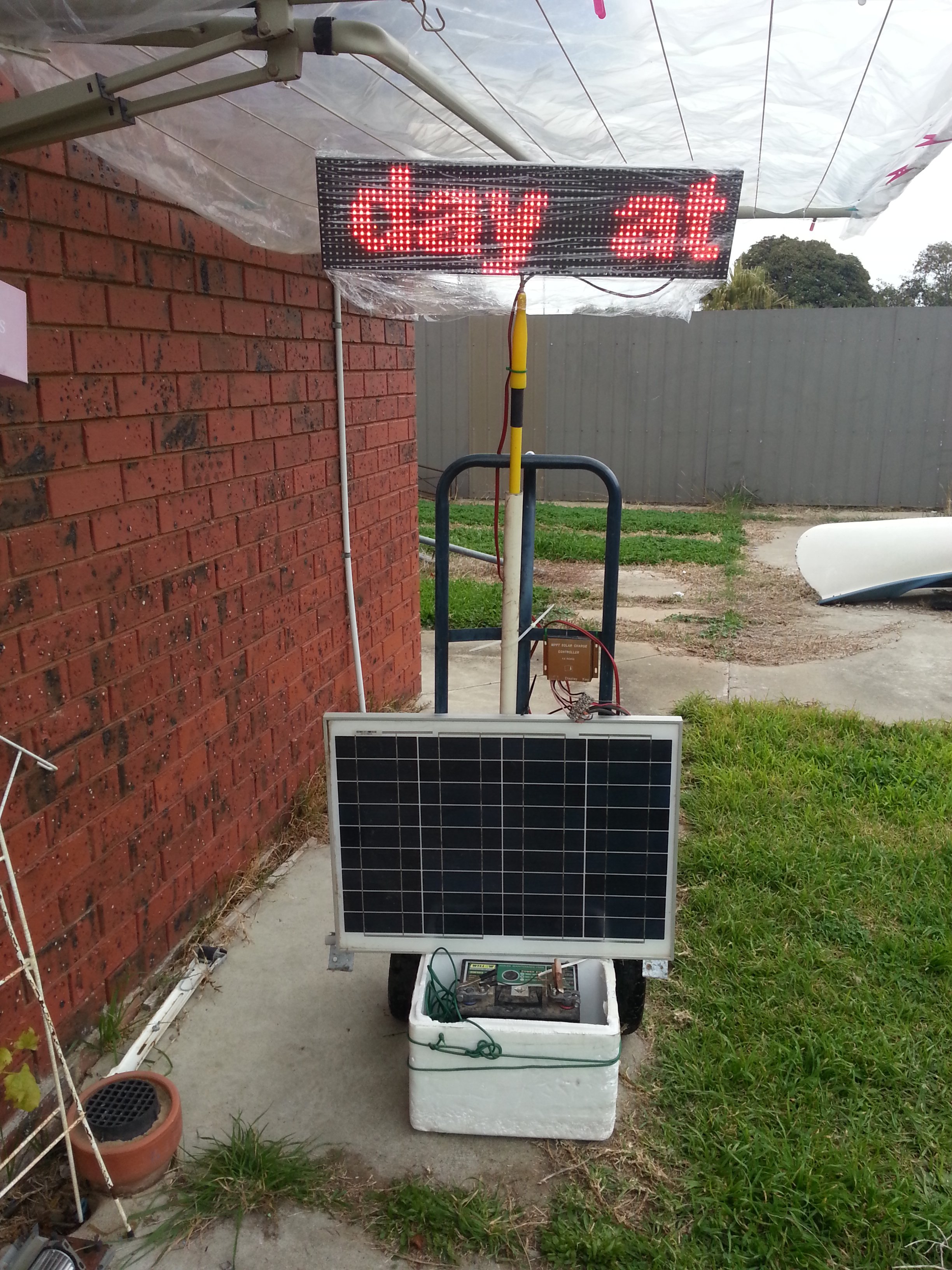
I will try to get something going for the next meeting.
 
Last edited:

VK3ZYZ

Moderator
Staff member
Here is my demo running through a sheet of paper to try for a better picture.
DMD-Master.zip is the library used.
P10_Demo.zip is the code.
Arduino_P10_Demo.zip is a movie.
EDIT: The code in post #85 is a bit better as it is easier to change as required.
 

Attachments

Last edited:

VK3ZYZ

Moderator
Staff member
Arduino_P10_lead.jpg

For the test, I wired a ribbon cable to some header pins to suit the Arduino.
But now I've soldered a header onto an Arduino Uno proto shield and run wires to the appropriate pins.

FYI, for those wanting to have a play, Jaycar in Shepp have displays of red, blue or white for around $20 to $30 depending on the LED colour.
 

VK3ZYZ

Moderator
Staff member
the VK3ZYZ_7Segx4 PCB has proto area so it can be pressed into service as an addaptor for the P10 display.
A 2x8 header is soldered on with the slot facing out.
P10_WiringTop.JPG
Note the black GND wire coming up through a hole to connect to the top of the gnd pin.


P10_WiringBtm_Labels.JPG
Here are the wire links installed. NOTE the orientation of the header!

And to power it all, use an old PC power supply.
P10_PowerLeads.JPG

EDIT: Pooh! I just noticed I put the wrong end on for the power. I'll fix it tomorrow after I thaw out.
 
Last edited:

VK3ZYZ

Moderator
Staff member
I figured out how to run more than one panel so for the demonstration day at Jaycar on the 15th, there will be 2 or maybe 3 panels in line.
SADARC_P10.jpg

At the moment, there are 2 different types of panels so they do not look the same. On the day, the panels will be identical.
See the comments in the code below for what to change to suit your application.

EDIT: I have taken the numbers out of the command and used labels to make it easier to understand and to change as required.
Thanks Daniel for your help :)

Code:
// Arduino P10 display based on....
// https://circuitdigest.com/microcontroller-projects/digital-notice-board-using-p10-led-matrix-display-and-arduino

#include <SPI.h>
#include <DMD.h>
#include <TimerOne.h>
#include "SystemFont5x7.h"
#include "Arial_black_16.h"

const char* message = "Welcome to the SADARC Amateur Radio and Electronics demonstration day at Jaycar ";

#define LEDs_across    32 // <<<< number of LEDs per panel width. In this case, the panels are 32x16.
#define ROW 2             // <<<< number of panels in line horizontally
#define COLUMN 1
#define FONT Arial_Black_16
#define ScanSpeed 10  // was originally 20 but that was a bit slow.
DMD led_module(ROW, COLUMN);

void scan_module()
{
  led_module.scanDisplayBySPI();
}

void setup()
{
  Timer1.initialize(2000);
  Timer1.attachInterrupt(scan_module);
  led_module.clearScreen( true );
}

void loop()
{
    led_module.selectFont(FONT);
    led_module.drawMarquee(message, strlen(message), (LEDs_across * ROW), 0);
    long start = millis();
    long timming = start;
    boolean flag = false;
    while (!flag)
    {
      if ((timming + ScanSpeed) < millis())
      {
        flag = led_module.stepMarquee(-1, 0);
        timming = millis();
      }  
    }
  }
 
Last edited:

VK3ZYZ

Moderator
Staff member
The panels are mounted on a couple of Aluminium strips.
SADARC_P10_Back.jpg


And a 3D printed base is on one end for the Arduino.
SADARC_P10_Uno.jpg
 

VK3ZYZ

Moderator
Staff member
The power supply has been cleaned up. Now, the Arduino is running on 5V as do the LEDs so the 12V is no longer needed. So, a 5V buck converter has been mounted on the frame and it is all powered from a 19V laptop supply brick.
Photo on 10-7-23 at 2.38 pm.jpg
 

VK3ZYZ

Moderator
Staff member
Looks good, will it run off a 12V car battery?
Thanks Ray.
It will run on 12v if the lead is changed. The power in is a screw terminal block. I do not think there is reverse polarity protection though. Maybe I will add a bridge rectifier and battery clip leads?
 

VK3YNV

Administrator
Staff member
That sounds good, we will be organizing a couple of big 12 V batteries, and not sure what mains inverters will be available, and we are setting up a long way from Jaycar, so extension leads might be a bit problematic. I will check on who is planning to bring mains inverters.
 

VK3YNV

Administrator
Staff member
Nice work, I'm thinking that can now go pretty much anywhere and not have to rely on mains. On Saturday we can work out the best spot, maybe even out on the nature strip where passing traffic can see it?
 

VK3ZYZ

Moderator
Staff member
I just received some boards from Lonely Binary. The came in a plastic bag with an Arduino cheat sheet printed on it, in RED!!!
This is the best scan I can get.
1689921170611.png

It may be of use.

EDIT: Terry, VK5TM just sent a better version as a pdf and it is attached below. Thanks Terry.
 

Attachments

Last edited:

VK3ZYZ

Moderator
Staff member
1690437167253.png

This is another board that is on the way.
It is a shield for an Arduino Uno or a board for a Nano.
Oh, I just noticed a typo :(
"Sheild" instead of Shield!
That does not mater too much. This shield has a connector for the P10 LED displays and the other unused pins brought out to sockets, with 2 sockets for I2C.
 
Last edited:

VK3ZYZ

Moderator
Staff member
I had a request for help to design an Arduino spark plug tester. The easy way for me to do it was to put an existing board into service. This board was designed as the ignition coil driver for a hail cannon. A hail cannon is a device to produce a LOUD boom directed skywards that in theory disrupts the formation of hail so as to protect orchards.

Photo on 5-8-23 at 7.08 pm.jpg


This is the board. An Arduino Nano drives the input and a simple code example is as follows...
Code:
#define buzzer 5    // pin used as the trigger signal

void setup() {
  pinMode (buzzer,OUTPUT);  // make it an output
}

void loop() {
  digitalWrite(buzzer,HIGH);  // pulse it HIGH
  delay(10);                  // wait 10mS
  digitalWrite(buzzer,LOW);   // then LOW to trigger the spark
  delay(1000);                // wait a second before repeating
}
This works ok, but for more fun, the babyelephantwalkPlus code is used instead.
A link on the modeSel pin 5 will just run the plain tester but removing the link will introduce the fun!

Please note, the examples written by Robson Couto (thanks ;)) use pin 11 for the buzzer but as I was reusing an old board, it was easier for me to use pin 5.
I have included the code examples from Robson Couto so you can play with them driving a Piezo speaker as intended, but is it much more fun to listen to the music from the arc!
I've attached a movie of a short section of it running. You can see the zaps of the standard mode of operation, then the first part of the "enhanced" test.

1691464092301.png
 

Attachments

Last edited:

VK3ZYZ

Moderator
Staff member
Photo on 7-8-23 at 1.53 pm.jpg

Now to see if they work!
EDIT: YES!
Photo on 7-8-23 at 6.45 pm.jpg

I did make the holes a bit small so it is a bit tricky to assemble but if all the pins are placed in and the board mounted on an Aduino BEFORE soldering it is ok.
The Arduino library item must be a bit out but that is odd as it has been used on other boards ok. ????
 
Last edited:

VK3YNV

Administrator
Staff member
Interesting new Arduino Nano.. The availability wifi opens up a lot of applications

Wifi enabled IC22S anybody?

 
Top