Learn Arduino?
- Thread starter VK3ZYZ
- Start date
Have you seen this series of posts?I have an ESP32 sitting here on the bench , have been trying to work out for a while what to do with it
VK3KFM
New member
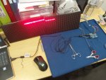
I have been playing with this led matrix code uploads fine but this is all I get any ideas??
Attachments
-
 2.4 MB Views: 279
Are you using the specified pins? It does make use of the SPI hardware I believe.I have been playing with this led matrix code uploads fine but this is all I get any ideas??
Looking at the picture, I'm unsure of your power connections.
The LED panels I have run on 5V only and it does look like you have maybe 12V connected as the Arduino barrel jack power seems to be the same as the panels. And the Arduino barrel jack needs to be at least 7V, not 5V.
Your Arduino will run ok on the laptop USB power but the LED panels will not.
Can you please clear up the connections?
Last edited:
Here is an updated source for a lot of info.
 randomnerdtutorials.com
Arduino: 39 Free Guides for Sensors and Modules | Random Nerd Tutorials
This article is a compilation of 39 free guides for different sensors, modules, and peripherals compatible with Arduino boards. The Arduino community has created a wide variety of modules.
randomnerdtutorials.com
For the next meeting 4th Nov. I will have a play with addressable LEDs.
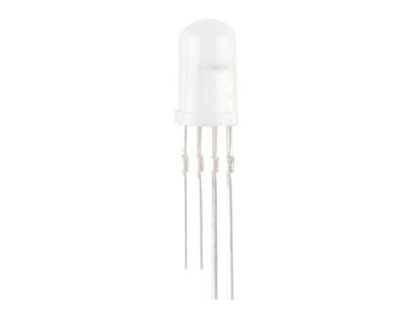
They come in different packages. This is an example.
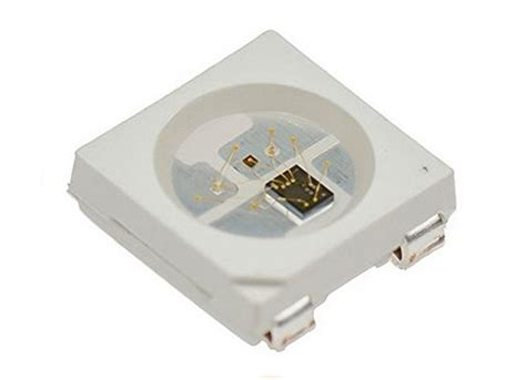
As is this...
Here are some libraries to add if you do not have them already.
See the postings about Josh's 5x8 matrix too.
They come in different packages. This is an example.
As is this...
Here are some libraries to add if you do not have them already.
See the postings about Josh's 5x8 matrix too.
Attachments
-
270.4 KB Views: 265
-
48 KB Views: 292
-
327.5 KB Views: 264
-
73.5 KB Views: 291
These may be a good board to play with.

 www.aliexpress.com
Aliexpress price $13 +$8 postage.
www.aliexpress.com
Aliexpress price $13 +$8 postage.
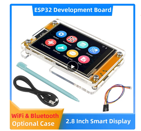
Have a look at this video. The guy in it has put a lot of work into getting a community going and has produced docs and code examples for this board. He does make a comment that there are other similar boards around so if you get one, check it is the correct one to suit the info.

 github.com
I think it could be a very fun board to play with. Maybe even run a radio synthesizer?
ESP32 MCU 2.8 Inch Smart Display for Arduino LVGL WIFI Bluetooth Touch WROOM 240*320 Screen LCD TFT Module with Free Tutorials - AliExpress 7
Smarter Shopping, Better Living! Aliexpress.com
Have a look at this video. The guy in it has put a lot of work into getting a community going and has produced docs and code examples for this board. He does make a comment that there are other similar boards around so if you get one, check it is the correct one to suit the info.
GitHub - witnessmenow/ESP32-Cheap-Yellow-Display: Building a community around a cheap ESP32 Display with a touch screen
Building a community around a cheap ESP32 Display with a touch screen - witnessmenow/ESP32-Cheap-Yellow-Display
github.com
I think it could be a very fun board to play with. Maybe even run a radio synthesizer?
Here is a great tool for playing with Arduinos.
It is an emulator that is described by Andreas Spiess ...
Hi youtube channel... https://www.youtube.com/@AndreasSpiess
My IC22S code on the emulator is here...
https://wokwi.com/projects/382507302478542849
Have a play with this okwi emulator. It is a great bit of work!
It is an emulator that is described by Andreas Spiess ...
My IC22S code on the emulator is here...
https://wokwi.com/projects/382507302478542849
Have a play with this okwi emulator. It is a great bit of work!
Here is a neat H bridge for motor driving that is very affordable, at under $15 each from the normal on line stores.
It is rated at 6 to 27V, and 30A (43A Max) so can drive quite large loads.
These were mentioned in the video refereed to in post #56.

Here is an article on driving them from an Arduino.
 dcc-ex.com

I will bring some along for the next SADARC meeting.
It is rated at 6 to 27V, and 30A (43A Max) so can drive quite large loads.
These were mentioned in the video refereed to in post #56.
Here is an article on driving them from an Arduino.
IBT_2 BTS7960 Motor Board — DCC-EX Model Railroading documentation
Hardware that works with EX-CommandStations or other DCC-EX products. [DCC-EX is a team of dedicated enthusiasts producing, easy to use, affordable, do-it-yourself, open source, DCC solutions to allow you to run your complete model railroad layout.]
I will bring some along for the next SADARC meeting.
Last edited:

I'm having a go at writing a non-3D printer bit of code for this board...
 It has all of the Arduino 2560 plus a lot more and just for under $35. Not at all bad!
You get 4 x stepper drivers on board. And if you are game, there is space for a couple more to be fitted.
Geeetech Motherboard High GT2560 V4.1B Quality Control Board for A10M 3D Printer | eBay Australia
1 x GT2560 V4.1B Motherboard. Pls check which board does your printer has before order. the board type will be written on the board itself. otherwise will not be compatible. Highly integrated and easy to assemble.
www.ebay.com.au
You get 4 x stepper drivers on board. And if you are game, there is space for a couple more to be fitted.
I got the board going ")
Set the board as.....
Board: "Arduino Mega or Mega 2560"
This sends "SOS" with the on board LED and a stepper motor noise.

Set the board as.....
Board: "Arduino Mega or Mega 2560"
This sends "SOS" with the on board LED and a stepper motor noise.
Attachments
-
2.1 KB Views: 105
Last edited:
As an example of recycled parts, here is a push button assemble from an old TV. It even had a plug to suit the hot bed temperature input "J6".

Test code....
#define T_Bed A10 // J16 pin 1
int ButtonPress = 0;
void setup() {
Serial.begin(9600);
}
void loop() {
ButtonPress=analogRead(T_Bed);
Serial.println(ButtonPress);
delay(1000);
}
The values are...
No button = 1023
AV/TV = 953
Menu = 997
V- = 892
V+. = 800
CH- = 560
CH+ = 0
Now I am hunting through my scrapped devices for suitable connectors for the limit switch inputs and the Fan "J10".
I will also be able to install FET "Q13" an the LED connector "J11" to expand the outputs.
There are the un-used U and U2 positions as well as the 6the stepper motor driver poets that I may try for a bit banged I2C port later.
I have modded the PCB. It was hndy to have an un-used motor position as that fits the I2C JST 4 pin connector.

A wire comes from R143 to connect the missing SDA.
And here are the others from H2 to connect the SCL and +5V. The gnd just comes from the close by copper.

And it works

And a small display...

A wire comes from R143 to connect the missing SDA.
And here are the others from H2 to connect the SCL and +5V. The gnd just comes from the close by copper.
And it works
And a small display...
Last edited:
I reckon it was an artwork error as the pin that is the SDA is labeled "LCM_RS" and the other "LCM_xx" pins go to the H2 connector for the display. And the LCD does need the RS signal so they changed the code to suit the pin "EC_PRESS" that was there instead. And that pin on the processor is next to the one that they should have used.
Last edited:
I've 3D printed a case to suit...


My test code is here too.
My test code is here too.
Attachments
-
3.5 KB Views: 102
Last edited:

I've modified a design by https://www.thingiverse.com/tonyrod as a good setup for learning Arduino.
The breadboards I have do not fit so that may be an extra version later.

Uno_BB_LCD_Controls by dendad51
This is a mod of https://www.thingiverse.com/thing:5329135 by https://www.thingiverse.com/tonyrodI t5hought that design pretty good, thank you :)The changes are..Remove most of the base of the breadboard to save a bit of time and filament.Make the screw holes fully through.Add a panel for...