Learn Arduino?
- Thread starter VK3ZYZ
- Start date
VK3BLD
Member
I have had one of these for quite a while. It outputs 5v and 3.3 vI just spotted this breadboard today..
View attachment 1284
Of course, you can get these cheaper on Ebay or similar, but this is on special for the next few days, and local, assuming they have them in stock.Solderless Breadboard with Power and I/O Breakout Board | Jaycar Electronics
Solderless breadboards are commonly used for prototyping because they allow you to quickly build temporary circuits without an iron. When finished or changing your circuit, it’s easy to take apart.www.jaycar.com.au
This comes with some jumper wires and a power feed in board.
Can you please tell me the size so I can see if it is the same as I have done the 3D prints for?I have had one of these for quite a while. It outputs 5v and 3.3 v
This one is about 165 x 54mm
EDIT: I think it is the same.
Last edited:
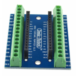
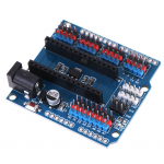
Some handy add-ons for an Arduino Nano.
This one make it easy to add wires to the board using screw terminals

One Ebay site of many...

And this version breaks out each I/O pin with a +V and Gnd as well. It also has an external power barrel jack.

Similarly.....

This one make it easy to add wires to the board using screw terminals

One Ebay site of many...

Nano Terminal Adapter Arduino Nano V3.0 AVR ATMEGA328P-AU Module Board MTCB^7K | eBay
You can use this adapter to easily hook up Arduino Nano to an outside world via hook up wires.
www.ebay.com.au
And this version breaks out each I/O pin with a +V and Gnd as well. It also has an external power barrel jack.

Similarly.....

NANO I/O expansion sensor shield module for arduino r3 n&7K | eBay
Find many great new & used options and get the best deals for NANO I/O expansion sensor shield module for arduino r3 n&7K at the best online prices at eBay!
www.ebay.com.au
Last edited:
A few years ago, FTDI released an "updated" USB driver. This was because the popular FT232RL USB to serial chip was being copied and sold for a lot cheaper price that the real ones. When you buy a board you do not know if it is a real or fake one, but the cheaper price could be a givaway.
The FTDI driver would detect the fake and brink them so they no longer worked. So, instead of going after those who are making the fakes, FTDI would punish the end user. This did not go down well.
As far as I know, this driver problem is only on the later Widows versions, not Macs.
I have a couple Arduinos that do not program anymore. I suspect the FTDI USB chips may be fake and they got bricked when used on my Windows 10 laptop.
I just found this site that tells how to unbrick them.

 electropit.com
A more details article on the differences...
 zeptobars.com
I will have to try this out and see if it fixes them.
If so, these will just stay as my Mac Unos!
Another complication is another USB driver chip that is in most boards now is the CH340. This driver is very buggy on the Mac, so I hope the FTDI fix works.
The FTDI driver would detect the fake and brink them so they no longer worked. So, instead of going after those who are making the fakes, FTDI would punish the end user. This did not go down well.
As far as I know, this driver problem is only on the later Widows versions, not Macs.
I have a couple Arduinos that do not program anymore. I suspect the FTDI USB chips may be fake and they got bricked when used on my Windows 10 laptop.
I just found this site that tells how to unbrick them.

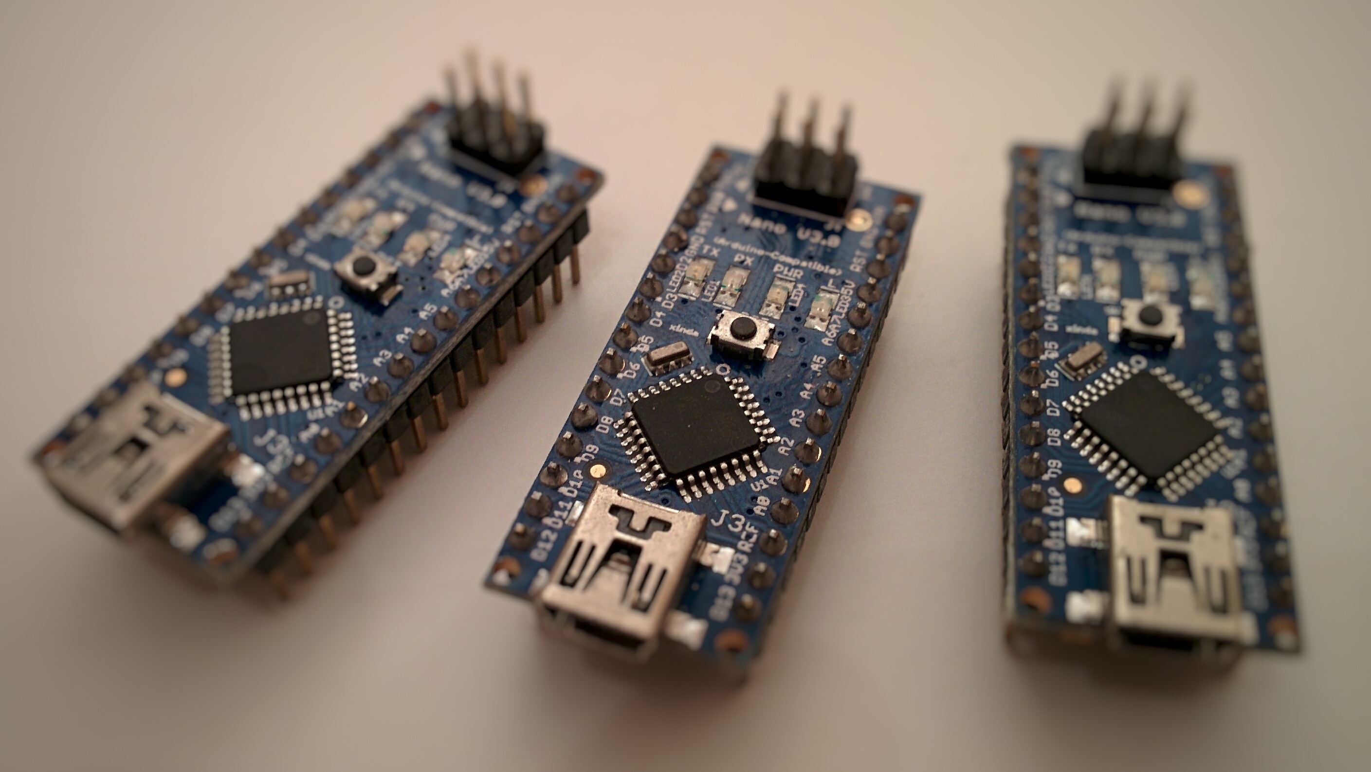
Arduino Nano v3.0 clones (How-to & Review)
If you need a breadboard-friendy, well documented and supported Arduino board, your best choice is a Nano. Unfortunately an original Arduino Nano could cost you around $30 plus shipping so it makes…
FTDI FT232RL: real vs fake : ZeptoBars
If so, these will just stay as my Mac Unos!
Another complication is another USB driver chip that is in most boards now is the CH340. This driver is very buggy on the Mac, so I hope the FTDI fix works.
The first Arduino starter course went a bit less well than it could have.
I had trouble sharing the laptop screen on the TV so had to look at the TV screen, not the laptop while typing.
Then, some had not go the Arduino going on their laptops before hand and I misplaced the USB stick I'd put the installers on. (one now is on my key ring). And the session was too short.
So, next month, we will try again. And more time will be allocated to it.
Please come along with Arduino IDE 1.8.19 installed, not the version 2 as I have no clue how to drive that one!
https://www.arduino.cc/en/software then select the one to suit your operating system.
Last edited:
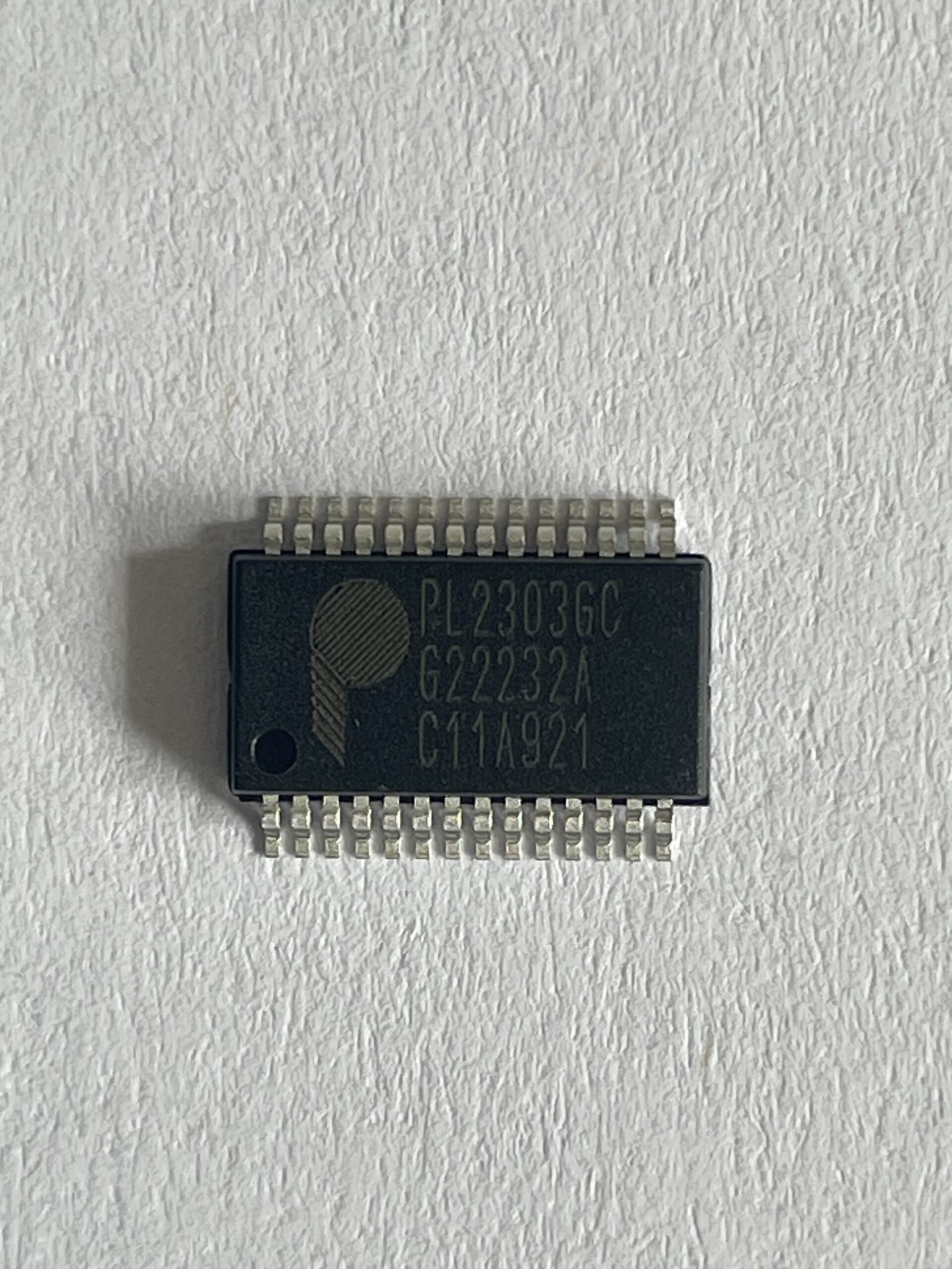
Josh pointed out the USB driver chips are not FTDI so that was a red herring.
No wonder I could not fix things by following the instructions!
It may be that Win10 no longer supports these chips. And the VAR micro's boot loaders are toast for some reason, and that is another matter.
Does anyone else who is coming to the course want the 3D printed base and panel as above?
Please let me know.
Hi Denys, I think the start of the course was OK . It is a big ask to get everything working first time 'round we are all at different levels of understanding. I am sure that all of us picked up useful information and with practice it might stick. With your help I was able to asign different output pins and make the LED flash with two different duty cycles. I shall continue to experiment . Thanks for running the course , may there be many more.
if i remember right they were prolific usb serial bridges.Josh pointed out the USB driver chips are not FTDI

PL2303GC USB to Full UART Bridge Controller with GPIO | Prolific USA | IC Design & Manufacturing
The PL2303GC is a low cost and high performance USB-to-Serial Bridge Controller. The PL2303GC provides a convenient small-factor solution for connecting an RS232-like full-duplex asynchronous serial device to any USB host. Prolific provides highly compatible drivers that could simulate the...
V
VK2RK
Guest
Save memory on Arduino trick
In your arduino code you will have print statements that print strings, to reduce the allocated memory for these strings here is an undocumented format
Example Serial.print ("MyString");
Replace it by adding the letter "F" to then look like this Serial.pring(F("MyString"));
Don't believe me ?
Compile your normal code then take a look at the memory used, then do the above and recompile and look at the reduction in memory used.
The F() function moves constant string variables to program memory freeing up space.
On the LCDs, I use an adapter board so they are driven from the I2C bus. This is just 2 data lines that are shared with other devices.

There are 3 address jumpers of a total of 8 displays could be used on the same pair of wires (plus 5V and gnd).
Here is some info on the one I use. (from https://handsontec.com/dataspecs/module/I2C_1602_LCD.pdf)
The circuit is this, more or less. When I get around to it, I may draw it out fully, but this is just hijacked from the links shown.

These interface boards can be used as a general I2C i/o port as well. For example, look at the posting for the IC22S Arduino control.
There are 3 address jumpers of a total of 8 displays could be used on the same pair of wires (plus 5V and gnd).
Here is some info on the one I use. (from https://handsontec.com/dataspecs/module/I2C_1602_LCD.pdf)
The circuit is this, more or less. When I get around to it, I may draw it out fully, but this is just hijacked from the links shown.
These interface boards can be used as a general I2C i/o port as well. For example, look at the posting for the IC22S Arduino control.
Attachments
-
879.6 KB Views: 512
V
VK2RK
Guest
The I2C is a very powerful feature that often is not understood by entry level users.
The I2C is a serial protocol developed by Philips back in the early eighties, its purpose was to reduce the componentry allowing control of separate modules be it in Industrial or Automotive applications later appeared in domestic products like TV and Video Recorders.

 en.wikipedia.org
The application today allows bidirectional data exchange at up to 3.4 Mb/s and 5 Mb/s unidirectional, the device has an individual address so that up to 1008 nodes (Devices) can be implemented utilizing the 10 bit address scheme.
As the Arduino provides a limited amount of ports, and the designed application requires to control more than what is provided there exist several ways to expand the capability, but using the I2C is by far the simplest way..
CAVEAT - The I2C is driven via the Arduino Interrupt system, here the function will only behave as well as the library code used allows, what I am saying as the Arduino as an open source platform there exists some real crappy library code, if having problems use an alternate library,
I found similar with the RS232 virtual port library on my GPS OCXO project.
There are many I2C I/O expansion modules for the Arduino available on the market that are not that expensive.
If designing an application that requires the acquisition or to drive outputs like relay and switches these modules will provide your design these requirements, a good solution.

 learn.adafruit.com
The I2C is a serial protocol developed by Philips back in the early eighties, its purpose was to reduce the componentry allowing control of separate modules be it in Industrial or Automotive applications later appeared in domestic products like TV and Video Recorders.

I²C - Wikipedia
 en.wikipedia.org
The application today allows bidirectional data exchange at up to 3.4 Mb/s and 5 Mb/s unidirectional, the device has an individual address so that up to 1008 nodes (Devices) can be implemented utilizing the 10 bit address scheme.
As the Arduino provides a limited amount of ports, and the designed application requires to control more than what is provided there exist several ways to expand the capability, but using the I2C is by far the simplest way..
CAVEAT - The I2C is driven via the Arduino Interrupt system, here the function will only behave as well as the library code used allows, what I am saying as the Arduino as an open source platform there exists some real crappy library code, if having problems use an alternate library,
I found similar with the RS232 virtual port library on my GPS OCXO project.
There are many I2C I/O expansion modules for the Arduino available on the market that are not that expensive.
If designing an application that requires the acquisition or to drive outputs like relay and switches these modules will provide your design these requirements, a good solution.

Adafruit MCP23017 I2C GPIO Expander
This Adafruit MCP23017 I2C GPIO Expander Breakout has 16 GPIO with matching ground pad. It runs happily from 3V or 5V logic and power. With 3 address pins, you can have up to 8 on a single bus for a total of 8 x 16 = 128 GPIO all on one I2C bus!
Last edited by a moderator:
