Learn Arduino?

VK3ZYZ

Moderator
Staff member
I have a couple of PCBs coming...
8727BandSelect.jpg

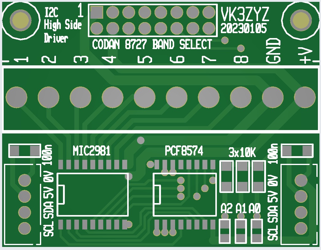
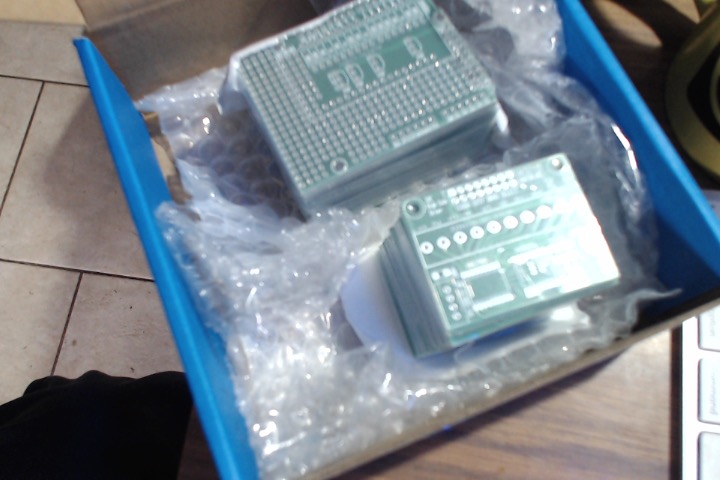
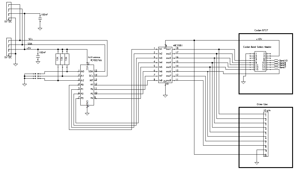
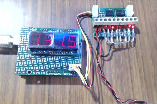
This is a 8 way I2c High Side Driver. It is for the Codan 8727 but also for general use when the screw terminals are fitted.


Arduino7seg.jpg


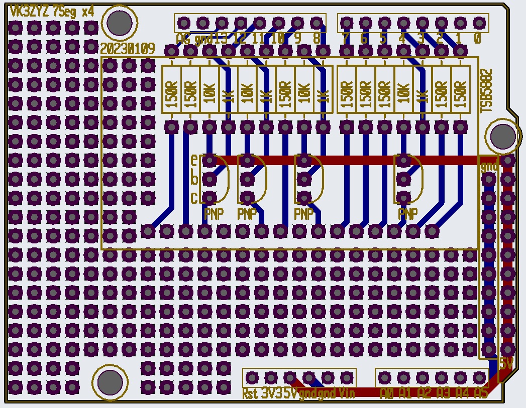
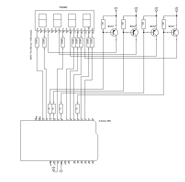
And a PCB for the 4x7Seg LED display we played with earlier. This should run brighter as there are transistors for switching.
There is plenty of proto area too.
 
Last edited:

VK3ZYZ

Moderator
Staff member
The boards are still in Sydney as far as I can see :(
They have been there for over a week.......

1675216984046.png
 

VK3ZYZ

Moderator
Staff member
I'm still hopeful that the PCBs will arrive in time.
If I've read the SevSeg libraries correctly, the setup for having PNP drivers on the Anodes will be as follows.
It was not really explained well at all.

void setup() {
byte numDigits = 4;
// pins in order to suit the TSB5882 display
// digits 1, 2, 3, 4 (staring from the left)
byte digitPins[] = {11,10, 8, 4};
// segment a, b, c, d, e, f, g, dp
byte segmentPins[] = {13, 7, 9,12, 5, 6, 2, 3};

bool resistorsOnSegments = true; // 'false' means resistors are on digit pins
/*
byte hardwareConfig = COMMON_CATHODE; // = 0 (digitOnVal=LOW, segmentOnVal = HIGH)
byte hardwareConfig = COMMON_ANODE; // = 1 (digitOnVal=HIGH, segmentOnVal = LOW)
byte hardwareConfig = N_TRANSISTORS; // = 2 (digitOnVal=HIGH, segmentOnVal = HIGH)
byte hardwareConfig = P_TRANSISTORS; // = 3 (digitOnVal=LOW, segmentOnVal = LOW)
byte hardwareConfig = NP_COMMON_ANODE; // = 0 (digitOnVal=LOW, segmentOnVal = HIGH)
byte hardwareConfig = NP_COMMON_CATHODE; // = 1 (digitOnVal=HIGH, segmentOnVal = LOW)
*/
byte hardwareConfig = P_TRANSISTORS; // PNP transistors on common Anodes. Arduino ports on Cathodes.

bool updateWithDelays = false; // Default 'false' is Recommended
bool leadingZeros = false; // Use 'true' if you'd like to keep the leading zeros
bool disableDecPoint = false; // Use 'true' if your decimal point doesn't exist or isn't connected

sevseg.begin(hardwareConfig, numDigits, digitPins, segmentPins, resistorsOnSegments,
updateWithDelays, leadingZeros, disableDecPoint);
sevseg.setBrightness(100);
}
 

VK3ZYZ

Moderator
Staff member
This workk to test the 8 way high side driver board, as long as the address is set correctly. For the PCF8574A with link A0 installed, the address is 0x3E.
 

Attachments

Last edited:

VK3ZYZ

Moderator
Staff member
The LED display works :)
SADARC_4x7LED_2_cct.jpg

The PCB has 150R resistors marked but as I did not have any, 220R have been used and the LEDs are bright enough and as a bonus, the didgit current is below the max for the BC557 transistors. Don't use 150R.
 
Last edited:

VK3ZYZ

Moderator
Staff member
The other board, the Codan 8727 Band Select, can be used for a general purpose high side 8 way driver.
Codan8727BandSelect.jpg

Address selection...
1676282430576.png
 
Last edited:

VK3ZYZ

Moderator
Staff member
Here is the data sheet for the MIC2981 chip used in the high side driver board.
It has 8 drivers, each of max 50V at 500mA. The total package current is 3Amps so it is a pretty handy board.
 

Attachments

VK3ZYZ

Moderator
Staff member
NOTE> If you use the PCF8574 chip, the address range is 0x20 to 0x27
If you use the PCF8574A chip, the address range is 0x38 to 0x3F
 

Attachments

VK3ZYZ

Moderator
Staff member
For this coming class, I thought it may be interesting to look at Ultrasonic Distance Sensing.
There are a number of types readily available, the HY-SRF04 with a TX and an RX unit as below. These cost less than $5 in Australia.
There is a SRF05 that looks similar and costs a bit more. I don't have any of those to compare the performance.


Photo on 28-2-23 at 1.51 pm.jpg


These DYP-ME007Y single unit sensors seem to work a lot better but are close to $20 from China.
Photo on 28-2-23 at 1.52 pm.jpg


JSN-SR04T Integrated Ultrasonic Module Distance Measuring Transducer N7K7 below features a fully sealed remote sensor. I have some of these but the magic "somewhere" comes into play!
These are a bit under $20 here from Oz.
1677552925517.png


There is a pretty good explanation of how these work at...
https://arduinogetstarted.com/tutorials/arduino-ultrasonic-sensor and they also publish some example code that we will try out at the lesson.
I'll bring printouts along for you to type in, or you could just download the files from the attached zip.
 

Attachments

VK3ZYZ

Moderator
Staff member
I've just been watching a very good Youtube video to do with these sensors.
This is from the Drone Bot Workshop channel.
His comment about the speed of sound through different mediums was quite good. See if you spot it. I've never thought of Pink Floyd being used to demonstrate a physics property!
 

VK3ZYZ

Moderator
Staff member
Just for interest, here is a video for the waterproof ultrasonic sensors mentioned earlier.
This sensor has some built in smarts and can operate in 5 modes...
1677914941536.png

Watch the video for details.
 
Last edited:

VK3ZYZ

Moderator
Staff member
This gent, Erik Meike, has modified the HC-SR04 sensor...
He taps into the analog out of the sensor...
1678949235180.png

and displays the signal on an OLED display....
1678949589773.png

Here you can see the echos of both his hand and the cardboard box.

I have not tried it as yet but here it is if anyone wants to have a play.
First, I have to install the ADC libs!
Also, this runs on a Teensy board, not a "standard" Nano, so that board will need to be installed too.
I have a Teensy somewhere so I may have a go at this.
 

Attachments

Last edited:
Top