IC22S Arduinoized?

VK3ZYZ

Moderator
Staff member
Install 2.54MM JST connectors under the PCB as shown. NOTE: The orientation as it is reversed WRT the silk screen on top. Another fix for #3 version of the PCB ;)
Originally I intended to have right angle connectors mounted on top but this way works ok.
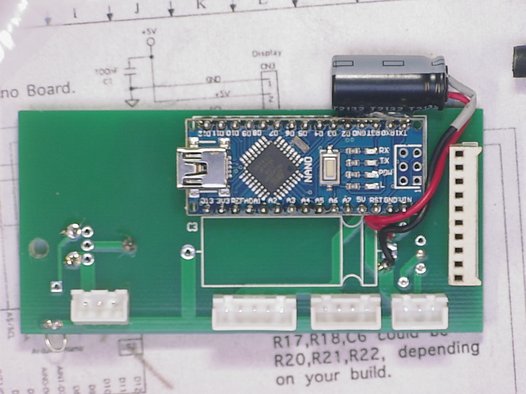
IMAG0419.JPG


And the wires may need to be swapped around to have the colours matching as below.
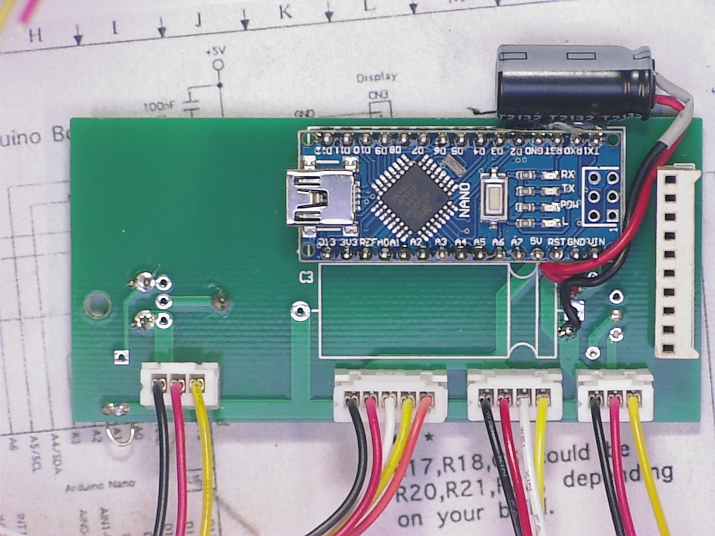
IMAG0421.JPG


Here is a closeup of the top of the PCB. (before it was cleaned).
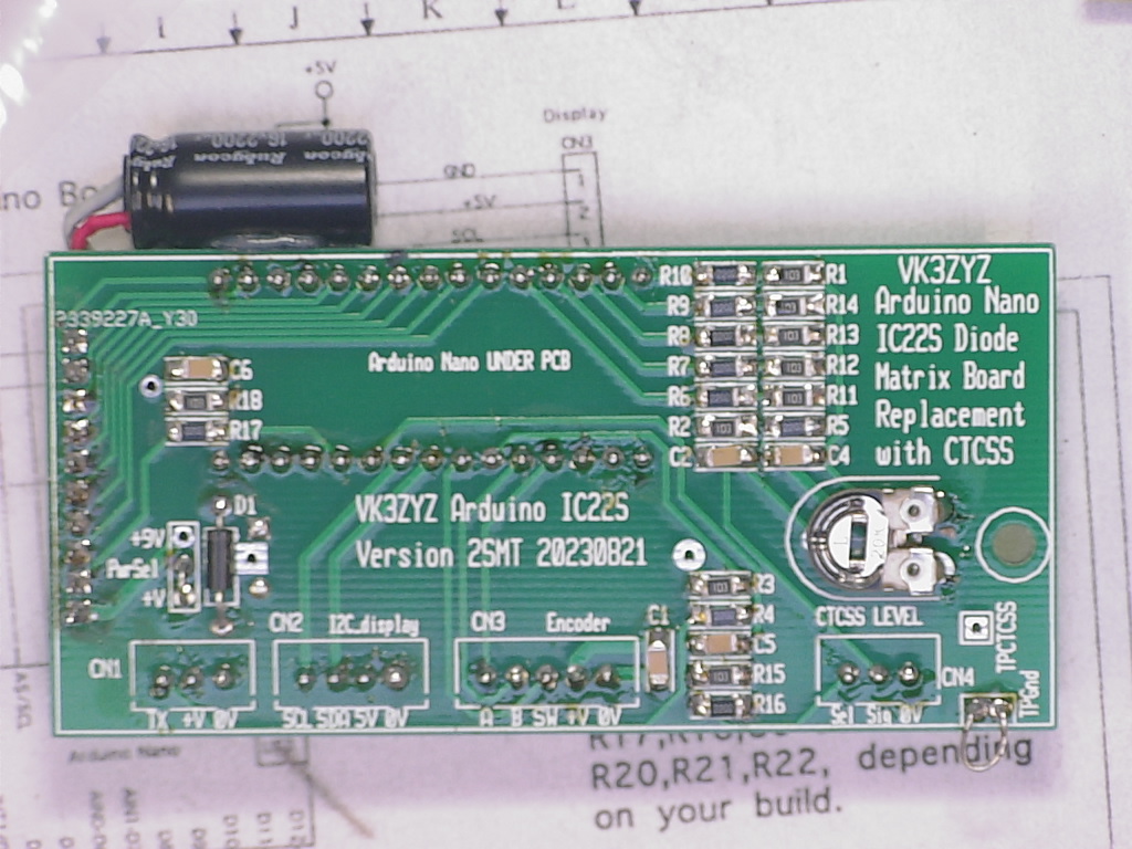
IMAG0420.JPG
 

VK3ZYZ

Moderator
Staff member
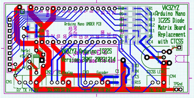
I may do a #3 PCB...

IC22S_Arduino3SMT.jpg


This will allow the old diode matrix connector or a straight one to be used.
Also, an alternate mount for the C3 electro as it needs to be thin.
Finally, this has A6 and A7 connection points.
 

VK3YNV

Administrator
Staff member
Here is the PDF, it's only 1.9 MB.

I just loaded it in Libre Office and exported as pdf. It's about half the size of the odt file.

I'm thinking I might re-arduinoize my IC22S, and get the latest mods. :)
 

Attachments

VK3ZYZ

Moderator
Staff member
Thanks ray.
I "printed" it as a .pdf, forgetting that I could just export i!
Do you want the SMT boards?
 

VK3YNV

Administrator
Staff member
Yes, save a set of the SMT boards for me, but supply all the others who want kits first, I'm in no hurry. The one I've got is working just fine, but the CTCSS addon would be good to have.
 

VK3ZYZ

Moderator
Staff member
The original board you have has the CTCSS built in already. The new SMT board adds a couple of analog inputs.
 

VK3ZYZ

Moderator
Staff member
I am still plodding along, trying to load and save settings to EEPROM but it is not working as yet.
The code IC22S_20240401nm.zip is the latest version but without any memory stuff.
 

Attachments

Last edited:

VK3ZYZ

Moderator
Staff member
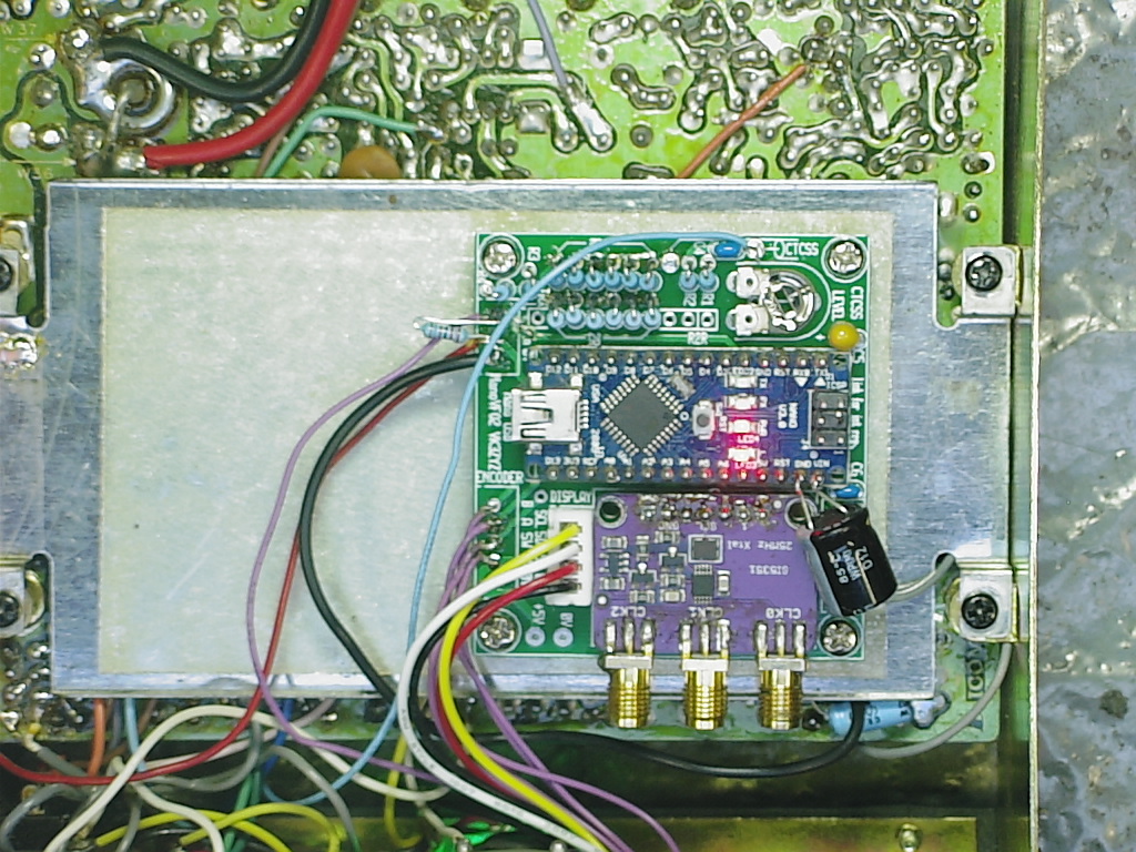
One of my IC22S sets has a crook PLL board so I grew te Arduino Nano VFO into it.
(I had a previous post about this but it looks like I accidentally deleted it).
IC22S_ArduinoNanoSynth.JPG


A handy mod for when working on sets is to add a connector to the speaker lead.
SpeakerMod.JPG

EDIT: 20250814 Updated code to fix an error in the CTCSS display routine.
 

Attachments

Last edited:

Josh

Active member
I decided to put a powerpole connector on my IC22S that i got from the hamfest several years ago.
I wanted to keep it all reversible, so i design a small plastic insert to take the place or the original molex style connector. The plastic should be printed with 100% infill so that it can be filed for a sung fit for your metal bracket.
m_4.jpeg m_6.jpeg m_2.jpeg m_1.jpeg m_7.jpeg
 

VK3EB

Active member
KM9G fast forward to 5min.40sec. The Arduinoized IC22 your project, but zero mention to link or any details


VK3ZYZ

Moderator
Staff member
I have an external PTT switch and mic setup for the IC22s.

1756949663746.png

In the IC22S, a 2K2 resistor is added from +9V to the mic socket pin 3 to power the LEDs.
When just on RX, the green LED lights, but on TX, then red LED is across the green and as it has a lower forward voltage, only the red LED illuminates. The diodes block the +12V from the PTT feeding back, and the extra diode in the green string just makes sure the red lights.
PTT_RX.jpg

PTT_TX.jpg

As the IC22S has an internal pullup on the mic connection, an electret mic can be used. I found an old mobile phone external mic works well. It is placed in front of the spedo in my car.
ElectretMic.jpg

There is non locking n.o. push button for the PTT, but also a toggle switch for long hands free overs. An option socket is added for a foot switch if required, All this in in a 3D printed case that is held onto the IC22S with a couple of magnets built into the bottom of the case, with a steel washer across them to increase the magnetism.
 
Last edited:
Top