I've been requested to have a look at a VFO for the TS-520S radio.
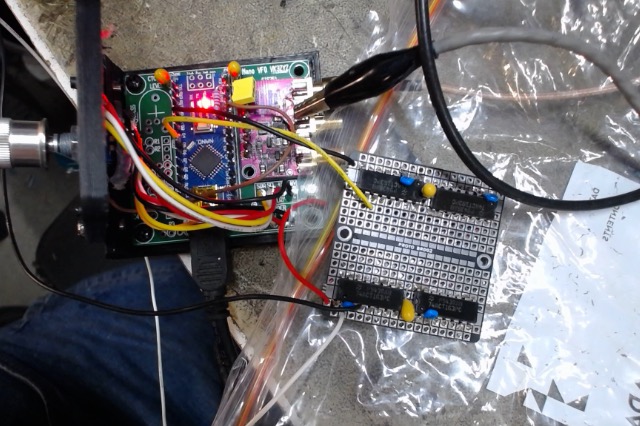
Using the Arduino Nano VFO will result in good stability and accuracy.
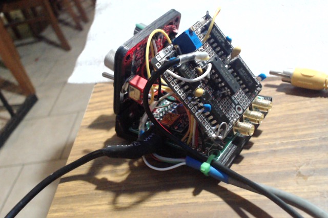
Here is my first run at this using one of my test rigs.
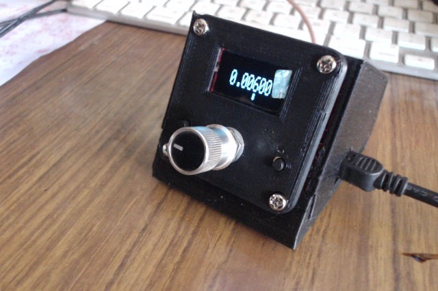
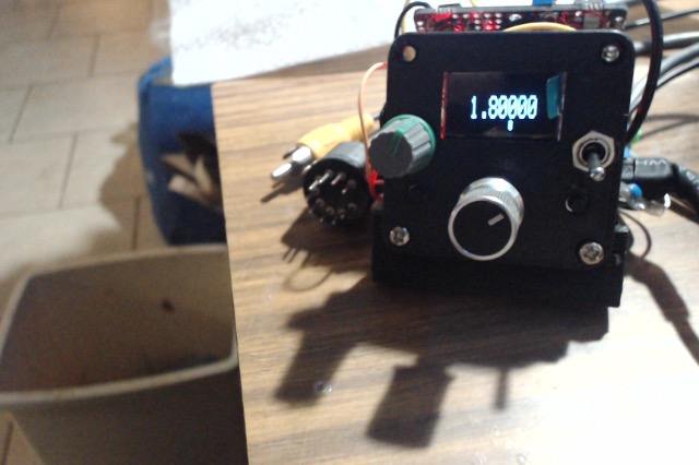
Pushing the encoder button allows each of the 5 decades to be selected for adjustment (shown by the * ) giving slow to fast tuning.
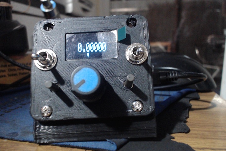
5.5Mhz output
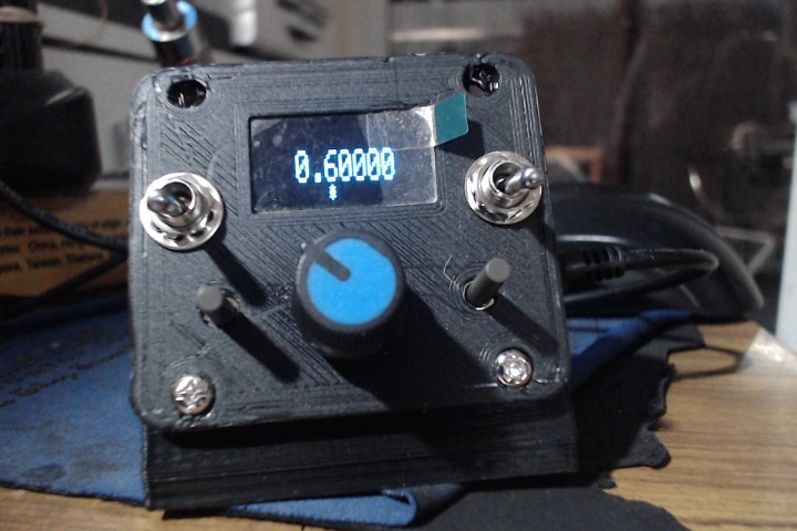
4.9Mhz output.
I'm not familiar with the TS-520S but it looks like the VFO needs to output 5.5Mhz for .000 reading and 4.9Mhz for .600 reading as this does.
What would be nice is to get a signal from the radio to tell the VFO what the band is so then the display could show the signal frequency directly.
That is something to look into.
So far, the RIT and various mode are not coded in, just the basic VFO.
Using the Arduino Nano VFO will result in good stability and accuracy.
Here is my first run at this using one of my test rigs.
Pushing the encoder button allows each of the 5 decades to be selected for adjustment (shown by the * ) giving slow to fast tuning.
5.5Mhz output
4.9Mhz output.
I'm not familiar with the TS-520S but it looks like the VFO needs to output 5.5Mhz for .000 reading and 4.9Mhz for .600 reading as this does.
What would be nice is to get a signal from the radio to tell the VFO what the band is so then the display could show the signal frequency directly.
That is something to look into.
So far, the RIT and various mode are not coded in, just the basic VFO.
Attachments
-
18.1 KB Views: 206
Last edited: