TS-520S VFO using the Arduino Nano VFO board. Then a custom PCB.
- Thread starter VK3ZYZ
- Start date
While playing round with the code today, I found switching to the set's internal VFO, the count set the external VFO frequ, so that is now a feature selected by pushing the encoder button when in internal VFO mode. So the external VFO frequency can be set from the internal VFO if required. Also, the frequency for each band is now remembered.
Work on the code continues with more cleaning up to be done. Some functions do not update the display correctly as yet.
Work on the code continues with more cleaning up to be done. Some functions do not update the display correctly as yet.
Last edited:
As of 20240806, this is the board I think will be the production version.
There are some changes to port allocations and an extra input to sense all the modes.


When I hack an "old" version 2 board to be this one, and modify the code, I'll post the latest code version.
All going well, working boards and code will be available in time for the SADARC Ham Fest on Sept. 8th.
There are some changes to port allocations and an extra input to sense all the modes.
When I hack an "old" version 2 board to be this one, and modify the code, I'll post the latest code version.
All going well, working boards and code will be available in time for the SADARC Ham Fest on Sept. 8th.
Attachments
-
119.1 KB Views: 161
I am having problems with the code.
Now, the encoder is not responsive, just every once and a while.
Now, the encoder is not responsive, just every once and a while.
Attachments
-
20.8 KB Views: 149
I had a look at the FreqCount.h files to see if I could reset the count to zero after selecting the VFO or HET input but I cannot understand the code 
Trying FreqCount.end(); then FreqCount.begin(); did not work for some reason, so I've been reading the count after switching and dropping that count to use the second read for an accurate count. All that delays a long time so that may be why the encoder is VERY slow.
Trying FreqCount.end(); then FreqCount.begin(); did not work for some reason, so I've been reading the count after switching and dropping that count to use the second read for an accurate count. All that delays a long time so that may be why the encoder is VERY slow.
This works 
Here is the lib.
Here is the lib.
Attachments
-
20.9 KB Views: 131
-
10.2 KB Views: 145
EDIT 20240823:
Here are updated files for 3D printing. There are 3 bases to hold pins of different sizes.
The 9 pin plugs are not that common now, so I have drawn up a plug for the radio and hope it fits ok. This has 10 holes for pins so it can be orientated in whatever way you want. A length of thin VGA cable will be put to use, maybe with a DB9 on the VFO end.

The link for the Tinkercad .... https://www.tinkercad.com/things/cJ1KYxEXHpU-ts520plug-set
And the small one suites the pins I took from a PCB mount DB25F.

The back pulls out and then the pins fall out of the housing.
Here are updated files for 3D printing. There are 3 bases to hold pins of different sizes.
The 9 pin plugs are not that common now, so I have drawn up a plug for the radio and hope it fits ok. This has 10 holes for pins so it can be orientated in whatever way you want. A length of thin VGA cable will be put to use, maybe with a DB9 on the VFO end.
The link for the Tinkercad .... https://www.tinkercad.com/things/cJ1KYxEXHpU-ts520plug-set
And the small one suites the pins I took from a PCB mount DB25F.
The back pulls out and then the pins fall out of the housing.
Attachments
-
115.5 KB Views: 113
Last edited:
Finally, the TS520 VFO is installed in a die cast box!

Here is the Version 3 in operation. The counter function has not been calibrated yet. The software is ripe for the fixing up. Please do!.

Running as a counter for the internal VFO.
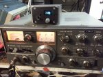
As an external VFO.
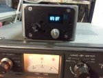
With the VFOs both off.
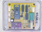
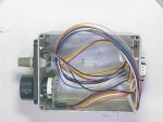
The PCB assembled.
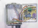
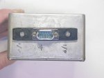
In the case. I could not be bothered to shorten the leads from the DB9.
I found some shielded 8 wire cable so wired that up to the 3D printed 9pin plug.
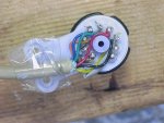
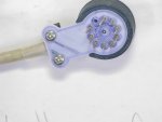
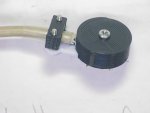
It looks pretty good plugged in!
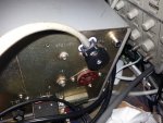
The other end goes to a DB9F plug.
Current code version is here.
Here is the Version 3 in operation. The counter function has not been calibrated yet. The software is ripe for the fixing up. Please do!.
Running as a counter for the internal VFO.

As an external VFO.

With the VFOs both off.

The PCB assembled.

In the case. I could not be bothered to shorten the leads from the DB9.
I found some shielded 8 wire cable so wired that up to the 3D printed 9pin plug.


It looks pretty good plugged in!

The other end goes to a DB9F plug.
Current code version is here.
Attachments
-
198.9 KB Views: 156
-
155.1 KB Views: 128
-
20.9 KB Views: 142
I did it yet again! SMOKE!!!
To check a pin size, I unplugged the 9pin plug and as my plug is very wobbly because I have yet to glue the pins in well, it was plugged back in one pin out (one of the pins was bent over).

My new box smoked, literally!
I was lucky! the 12VAC wire was hooked to GND so only the wire smoked
To check a pin size, I unplugged the 9pin plug and as my plug is very wobbly because I have yet to glue the pins in well, it was plugged back in one pin out (one of the pins was bent over).
My new box smoked, literally!
I was lucky! the 12VAC wire was hooked to GND so only the wire smoked
I found a stack of these DB25 plugs so the pins look to be quite suitable for the 9pin plug needed. A 3D printed plug body and 10 pins (one spare) will be included in the Ham Fest kit, along with the main and switch PCBs and the relay.
Post #50 has been updated for the latest 3D print files.
Last edited:
Ray kindly gave me a length of neat cable. It is a little over 6mm in diameter but has an outside shield and then 8 individually shielded pairs!
Yes, 16 wires in it. The pairs shields are insulated from the others too.
Here are the steps I took to make the cable...
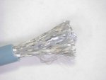
Strip about 4cm.

Separate the pairs.

Remove the insulated layer from each pair, then the shield single wire (these are all later joined to signal gnd).
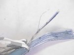
If I was paying attention, I may have been able to make use of the pair's numbers. A short length of heat shrink was placed over the pair to keep them together.

It starts to get a bit crowded. Here you can see the single shield wired twisted together.
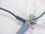
A green for the signal shields and black for the power ground (main shield).
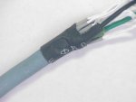
Heat shrink-ed.
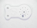
Decide on the orientation you want the plug to go and mark the unused pin.
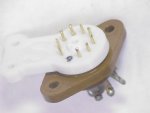
Use a spare 9pin socket to insert the pins (I had to ream out a couple of the holes in the 3D printed part) and seat them firmly into the socket. Then trim them off to about 3mm.
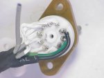
Here I have soldered the wires on, and there is one spare.
I found the lid has to be trimmed a bit foe the wires are a bit wide for the slot. Also, I drilled the hole out to 3mm.
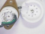
The base part was tapped for M3 to suit the screw, but you may find a self tapper suitable.
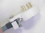
Similarly, the base strain release holes were drilled to 3mm and the clamp tapped M3.
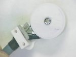
I still have to get some DB9H connectors, I have LOTS of DB9Ms.
This all went together pretty well, even though it is a bit fiddly.
Thanks Ray
Yes, 16 wires in it. The pairs shields are insulated from the others too.
Here are the steps I took to make the cable...

Strip about 4cm.

Separate the pairs.

Remove the insulated layer from each pair, then the shield single wire (these are all later joined to signal gnd).

If I was paying attention, I may have been able to make use of the pair's numbers. A short length of heat shrink was placed over the pair to keep them together.

It starts to get a bit crowded. Here you can see the single shield wired twisted together.

A green for the signal shields and black for the power ground (main shield).

Heat shrink-ed.

Decide on the orientation you want the plug to go and mark the unused pin.

Use a spare 9pin socket to insert the pins (I had to ream out a couple of the holes in the 3D printed part) and seat them firmly into the socket. Then trim them off to about 3mm.

Here I have soldered the wires on, and there is one spare.

I found the lid has to be trimmed a bit foe the wires are a bit wide for the slot. Also, I drilled the hole out to 3mm.


The base part was tapped for M3 to suit the screw, but you may find a self tapper suitable.

Similarly, the base strain release holes were drilled to 3mm and the clamp tapped M3.

I still have to get some DB9H connectors, I have LOTS of DB9Ms.
This all went together pretty well, even though it is a bit fiddly.
Thanks Ray

