TS-520S VFO using the Arduino Nano VFO board. Then a custom PCB.

VK3ZYZ

Moderator
Staff member
I've been requested to have a look at a VFO for the TS-520S radio.
Using the Arduino Nano VFO will result in good stability and accuracy.
Here is my first run at this using one of my test rigs.
Pushing the encoder button allows each of the 5 decades to be selected for adjustment (shown by the * ) giving slow to fast tuning.
Photo on 18-4-24 at 7.17 pm.jpg

5.5Mhz output


Photo on 18-4-24 at 7.17 pm #2.jpg

4.9Mhz output.

I'm not familiar with the TS-520S but it looks like the VFO needs to output 5.5Mhz for .000 reading and 4.9Mhz for .600 reading as this does.
What would be nice is to get a signal from the radio to tell the VFO what the band is so then the display could show the signal frequency directly.
That is something to look into.

So far, the RIT and various mode are not coded in, just the basic VFO.
 

Attachments

Last edited:

VK3ZYZ

Moderator
Staff member
A test with feeding the VFO into the rear RCA connector seems to work on RX but not on TX as then the set reverts to the internal VFO. A bit more study of the manual is needed to figure out the operation.
 

VK3ZYZ

Moderator
Staff member
Photo on 28-04-2024 at 3.26 PM.jpg

I'm playing around with a 16 stage divider fed from the TS520S band selected HET crystals, the resultant frequency is counted by the Arduino Nano then used to set the band. The VFO will display the signal frequency and also limit the VFO range to prevent out of band transmissions.
It does look like it will work after some calibration, but I will still need to test this on the real set.
 

VK3ZYZ

Moderator
Staff member
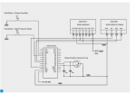
This is an updated circuit 20240509. I think it may work ok with the VFO on both TX and RX when selected from the TS520S.
The 74xx chips used as amps have been tossed in favor of a simple transistor amp.
1715293072826.png


The case no longer fits..
Photo on 30-4-24 at 8.12 pm.jpg
Photo on 30-4-24 at 8.12 pm #2.jpg

I have not included the filter as yet.
Here is the latest code.
Now, I just need to test it in a radio!!!!
 

Attachments

Last edited:

VK3ZYZ

Moderator
Staff member
I think the code is done now!

EDIT: 20240510. The code will need to be changed as I have swapped some pins on the PCB layout to make it easier to draw. But I may wait until I have some boards to play with before doing that.
 

Attachments

Last edited:

VK3ZYZ

Moderator
Staff member
1715292414925.png

UPDATE 20240510. This looks ok I think.

1715292515911.png

Sub board for the function switch.
 
Last edited:

VK3ZYZ

Moderator
Staff member
As far as I can see, this is the TS520S and VFO520 switch positions.
Not all the switches are done but I think this will be enough to go with.

FIX​
RMT​
25KHz​
VFO​
VFO-R​
FIX-R​
FIX​
S2-1 FIX +V​
VOX delay 9V​
nc​
nc​
nc​
RLT​
RLR​
VOX delay 9V​
S2-2 Ext VFO (9)​
9V​
9V​
9V​
9V​
RLR​
RLT​
nc​
S2-3 CAL​
nc​
VFB​
nc​
nc​
nc​
nc​
nc​
S2-4 9V​
nc​
EXT VFO ( 6)​
Marker Carrier​
Carrier​
Carrier​
Carrier​
Carrier​
TUNE​
CW​
USB​
LSB​
S3-1 CWT​
9V​
RTL​
nc​
nc​
S3-2 CWR​
nc​
RLR​
nc​
nc​
S3-3 9V​
nc​
nc​
9V​
9V​
S3-4 VOX in​
nc​
STO​
VOX gain pot​
VOX gain pot​
S3-5 AntiVox​
nc​
gnd​
Avox pot​
Avox pot​
S3-6 gnd​
Key​
STE​
key​
key​
S3-7 BalModIn​
CarrierMod​
CarrierMod​
MicAmpOut​
MicAmpOut​
S3-8 14V​
SSB​
SSB​
SSB​
SSB​
VFO-520​
OFF​
REC​
REC/XMIT​
XMIT​
<<< EXT VFO function​
S1-1 EXT VFO 9V​
nc​
RX J1 (9)​
J1 (9)​
TX J1 (9)​
S1-2 J1 (8) (int VFO power)​
J1 (9)​
TX J1 (9)​
nc​
RX J1 (9)​
S1-3 J1 (6) 9V on RMT select​
EXT VFO 9V​
J1 (8)​
J1 (8)​
EXT VFO 9V​
J1 (6) = 9V on RMT select​
J1 (8) = Int VFO +V in​
J1 (9) = VFO +V supply​

For no external VFO use, J1 (8) and J1 (9) are linked to feed the internal VFO power.
 

VK3ZYZ

Moderator
Staff member
The 9 pin plugs seem to be a bit of a rare item, so I made one...
The 9 pin sockets are still available on Ebay...
1715405971546.png

and I have a stack of these special leads...
Photo on 11-5-24 at 3.16 pm.jpg

The mini XLR plugs have gold plated pins that are just the size needed.
Photo on 11-5-24 at 3.17 pm.jpg

so, after chopping 3 plugs open, the pins were soldered to the socket...
1715406112386.jpeg

and a 3D printed cover made to suit!
Photo on 11-5-24 at 3.21 pm #2.jpg

The cover has a hole for an M3 screw with a nut recess in it to be used to hold it all together. A cable tie will be used to hold the cable.

It looks to be a working fix.
 

VK3ZYZ

Moderator
Staff member
An update re the PCBs...
Last night, my iMac died. It was saying the drives had not been ejected correctly. So. I clicked on the OK button and the screen went white. There is no "ding" on start up :(
Hopefully, the HD is ok and if so, I had already produced the zipped Gerbers so getting the PCBs made should be ok. One problem if I cannot get it going again is my PCB package is keyed to the machine and I'll have to ask the US program suppliers to reset my keys so the programs can be reinstalled on another Mac.
 

Josh

Member
An update re the PCBs...
Last night, my iMac died. It was saying the drives had not been ejected correctly. So. I clicked on the OK button and the screen went white. There is no "ding" on start up :(
Hopefully, the HD is ok and if so, I had already produced the zipped Gerbers so getting the PCBs made should be ok. One problem if I cannot get it going again is my PCB package is keyed to the machine and I'll have to ask the US program suppliers to reset my keys so the programs can be reinstalled on another Mac.
Oh no!
hope ur back up and running again. feel free to reach out if you need anything.
 

VK3ZYZ

Moderator
Staff member
Arthur has lent me a TS520D to test the VFO on, but the "D" version looks to not have the HET signal extended. I will have to add an RCA connector and a buffer amp as that signal is use to determine the band in use.
 

VK3ZYZ

Moderator
Staff member
I will get back to this soon as I'm just over a 2 week stint in bed with a crook back. There are quite a few things I have to catch up on.
 

VK3ZYZ

Moderator
Staff member
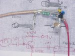
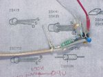
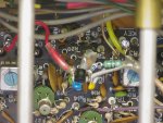
The TS520D lent to me for development does not have the "HET" signal extended so here is the mod to install a buffer amp. It was a birds nest construction.
An RCA socket was added to the rear to feed the ext VFO so it can be used to determine the band selected.
1719999045321.png


TS520D_HetBuffer1.JPG
TS520D_HetBuffer2.JPG
TS520D_HetBuffer3.JPG
 
Top