Server Powersupply mod
- Thread starter VK3ZYZ
- Start date
I was having a lot of trouble printing a new cover....
These all stopped printing with jammed filament about half way through the print.
In the process of the black PLA prints, I had to pull the hot end apart to remove the filament and found it was a bit loose. That was the problem, I hoped. But no!
So, maybe the black is the problem?
Well, you can see that changing to the grey did not fix it.
To do these prints, I have changed the slicer program used. The slicer is the program that converts the drawing .stl file into the .gcode the printer understands. This new version has a setting to keep the holes the correct size. Using the older version of the slicer, the holes turned out smaller that set so I'd fiddled the hole sizes to fix that. The setting in the slicer does the "fiddling" for me now. As a result of using the new slicer I may go and redo the old files.
Anyway, it turns out the problem with the print stopping looks to the the retraction setting in the new slicer. The retraction is the filament being pulled back into the printer a bit so there will not be melted filament oozing out while the head is moving and not printing.
Mr Google showed one cause of the filament jamming could be the retraction set too high. If it is, more heat gets transfered up into the cold part of the hot end eventually causing the filament to melt too early so causing a jam.
The retraction was set at 6.5mm and a change to 2.5mm fixed it")
This version starts out with black for 3 layers, then I change to orange for a bit, then back to black.
These all stopped printing with jammed filament about half way through the print.
In the process of the black PLA prints, I had to pull the hot end apart to remove the filament and found it was a bit loose. That was the problem, I hoped. But no!
So, maybe the black is the problem?
Well, you can see that changing to the grey did not fix it.
To do these prints, I have changed the slicer program used. The slicer is the program that converts the drawing .stl file into the .gcode the printer understands. This new version has a setting to keep the holes the correct size. Using the older version of the slicer, the holes turned out smaller that set so I'd fiddled the hole sizes to fix that. The setting in the slicer does the "fiddling" for me now. As a result of using the new slicer I may go and redo the old files.
Anyway, it turns out the problem with the print stopping looks to the the retraction setting in the new slicer. The retraction is the filament being pulled back into the printer a bit so there will not be melted filament oozing out while the head is moving and not printing.
Mr Google showed one cause of the filament jamming could be the retraction set too high. If it is, more heat gets transfered up into the cold part of the hot end eventually causing the filament to melt too early so causing a jam.
The retraction was set at 6.5mm and a change to 2.5mm fixed it
This version starts out with black for 3 layers, then I change to orange for a bit, then back to black.
Last edited:
A worthwhile simple mod on the R2Z-6400P-R 28Amp version is to unplug the two 12V fans and hook them onto 5V. I kust taped the connectors together, bent a couple pieces of wire (resistor lead) into U shapes so they plug both "12V" connections together and same for the 0V. Then soldered a length of hookup wire to these links and ran them to the PS 5V and 0V connections.
Now, the fans run quietly, instead of as sirens!
Now, the fans run quietly, instead of as sirens!
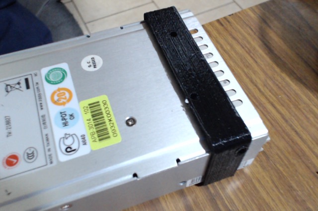
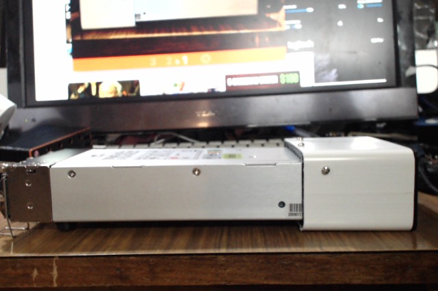
I'm thinking of using some PVC down pipe for the case as it will be a lot easier and faster to produce. There will have to be a few adapters made to fit as the pipe is bigger the the power supplies, but here is the first "working" effort.
The front is similar to the earlier ones...
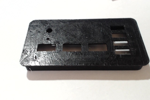
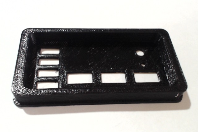
but being removable will make wiring a lot easier.
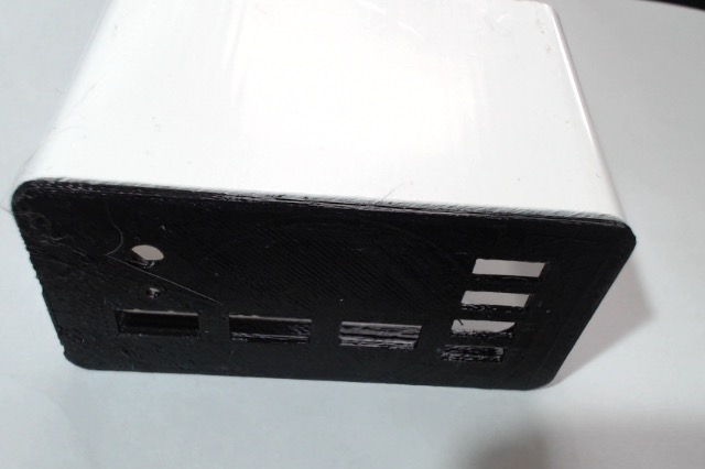
It fits ok, and will have screws in from the sides, top and bottom.
The front is similar to the earlier ones...
but being removable will make wiring a lot easier.
It fits ok, and will have screws in from the sides, top and bottom.
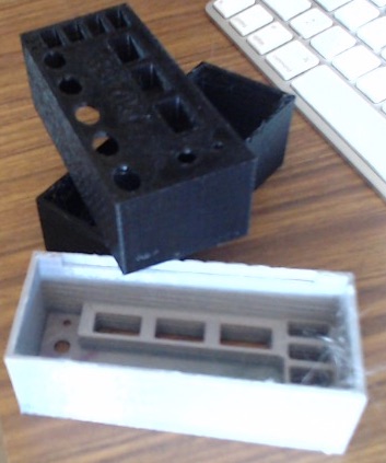
Here it is all printed out.
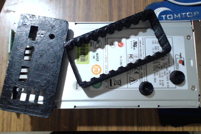
There is a front, spacer and rear feet.
The spacer has air channels.
Feet can be fitted at the rear to level it.
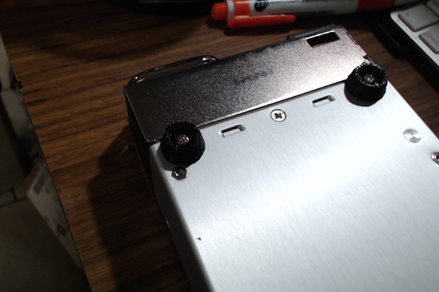
I have not installed the 12V sockets as yet.
The fully 3D printed case may be neater but it takes a long time to print.
There is a front, spacer and rear feet.
The spacer has air channels.
Feet can be fitted at the rear to level it.
I have not installed the 12V sockets as yet.
The fully 3D printed case may be neater but it takes a long time to print.
Last edited:
Here are the steps to wire it up to a connector that has been cut off the power supply cradle chassis.
First, the power switch and LED. Note the 220R resistor in line with the LED.

Next, the USB sockets. I have included a 5A Polyswitch, and no USB resistors.

Now to thea12V. I used Jaucar flat speaker wire as it is very flexible, and has a lot of copper.


The fans normally run on 12V and if you like sirens, you can keep it that way. I prefer a quieter supply so here are the steps to change to 5V operation.
First, take the PS top off.

The fans need to be unplugged. There will be white gunk that needs to be cut to free the plugs.
A couple of wire links bent to fit..

and the connectors wired together.

then secured with heat shrink or tape
.
Finally, with the top put back and the mounting sleeve fitted, the fan wires can be attached to the socket.

It works
( I used my soldering iron to "drill" screw holes in each side to hold the front on.)
First, the power switch and LED. Note the 220R resistor in line with the LED.
Next, the USB sockets. I have included a 5A Polyswitch, and no USB resistors.
Now to thea12V. I used Jaucar flat speaker wire as it is very flexible, and has a lot of copper.
The fans normally run on 12V and if you like sirens, you can keep it that way. I prefer a quieter supply so here are the steps to change to 5V operation.
First, take the PS top off.
The fans need to be unplugged. There will be white gunk that needs to be cut to free the plugs.
A couple of wire links bent to fit..
and the connectors wired together.
then secured with heat shrink or tape
.
Finally, with the top put back and the mounting sleeve fitted, the fan wires can be attached to the socket.
It works
( I used my soldering iron to "drill" screw holes in each side to hold the front on.)
Last edited:
Here is another. Thanks to Josh for the connections to get is going.
This is for the TDPS-750AB A unit that is 750Watts.
The main connector has +12V at 54Amps, +5V at 33Amps and 0V pins. I just soldered heavy cables onto the pins as I've not got a connector.
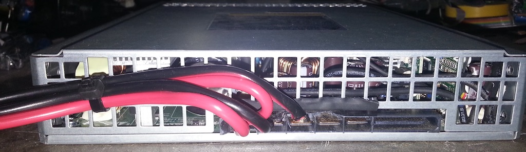
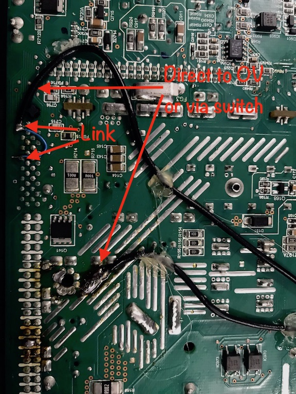
Josh sent me the info to get it working. In his picture, there are a couple of black wires going to an on/off swicth. (I just linked direct to0V and used the power switch.)
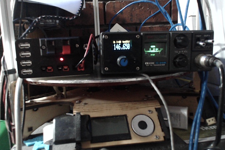
This is a nice flat power supply so your set could well sit on top of it. About 280x210x40.
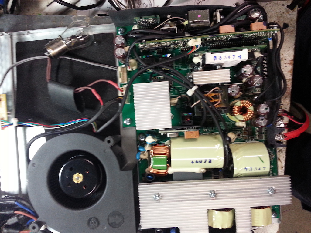
One problem is the 2 fans installed are 12V at 6A!!!! They make great blower fans, or sirens if you prefer. And the power supply shuts down if the fans fail to get to speed.
There may be a hardware mod for this but my fix was a bit different.
Both fans were removed and the one with the longer leads replaced but turned 180 degrees so it now blows onto the main power supply heat sink.
First, I tried running the fan on 5V but it would not start. Then on 7V from en external power supply as 7V looks to be the minimum voltage to get it going to keep the supply alive. But the fan is still too loud. Next, running through various power resistors but that was not satisfactory. Another try was to use series diodes to drop the voltage, In this case, I have a bag of W04 bridge rectifiers so 3 of them in line dropped the voltage ok but they got hot and the fan is still too noisy.
The final fix I came up with is to cut the fan red wire and install a 12V 5W tail light lamp in series. This lets the fan speed up when the lamp is cold, then slows as the lamp heats. As the fan now slows down, the lamp cools so the fan speeds up again. This repeats so the power supply "breaths" but keeps working and has air to cool it.
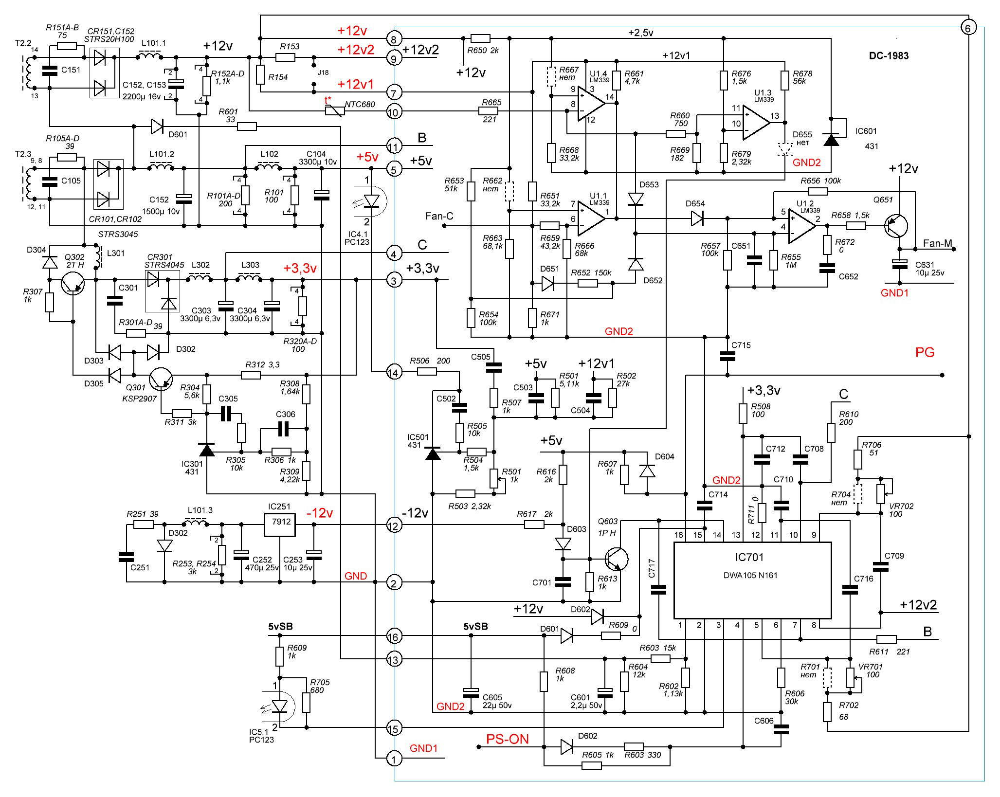
There was a web site than came up with maybe a part of the circuit...
Another fan mod I hope to try is to add one of my PIC12F629 boards into the fan tacho line to double (or more) the pulse frequency to see if that can get the fan running slowly. And to increase the 12V to 13.8V too!
This is for the TDPS-750AB A unit that is 750Watts.
The main connector has +12V at 54Amps, +5V at 33Amps and 0V pins. I just soldered heavy cables onto the pins as I've not got a connector.
Josh sent me the info to get it working. In his picture, there are a couple of black wires going to an on/off swicth. (I just linked direct to0V and used the power switch.)
This is a nice flat power supply so your set could well sit on top of it. About 280x210x40.
One problem is the 2 fans installed are 12V at 6A!!!! They make great blower fans, or sirens if you prefer. And the power supply shuts down if the fans fail to get to speed.
There may be a hardware mod for this but my fix was a bit different.
Both fans were removed and the one with the longer leads replaced but turned 180 degrees so it now blows onto the main power supply heat sink.
First, I tried running the fan on 5V but it would not start. Then on 7V from en external power supply as 7V looks to be the minimum voltage to get it going to keep the supply alive. But the fan is still too loud. Next, running through various power resistors but that was not satisfactory. Another try was to use series diodes to drop the voltage, In this case, I have a bag of W04 bridge rectifiers so 3 of them in line dropped the voltage ok but they got hot and the fan is still too noisy.
The final fix I came up with is to cut the fan red wire and install a 12V 5W tail light lamp in series. This lets the fan speed up when the lamp is cold, then slows as the lamp heats. As the fan now slows down, the lamp cools so the fan speeds up again. This repeats so the power supply "breaths" but keeps working and has air to cool it.
There was a web site than came up with maybe a part of the circuit...
Another fan mod I hope to try is to add one of my PIC12F629 boards into the fan tacho line to double (or more) the pulse frequency to see if that can get the fan running slowly. And to increase the 12V to 13.8V too!
Last edited:
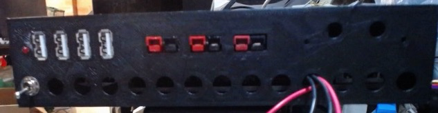
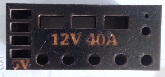
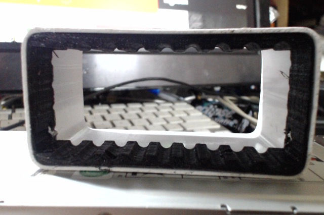
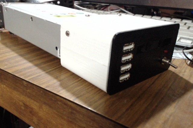
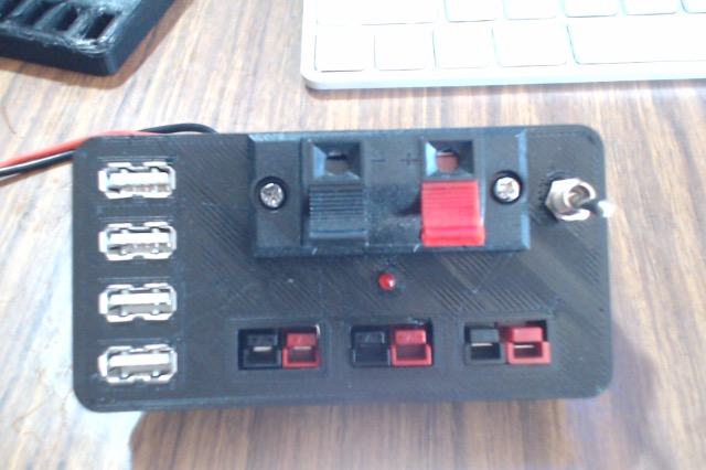
Here is the latest version front for the server power supply mod making use of the 100x50mm PVC down pipe for the case.
The spacers are still to be printed, but enough for tonight!
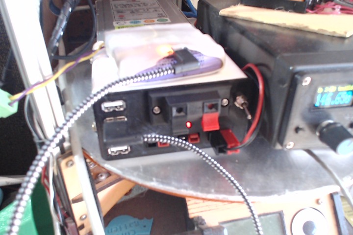
I've added a spring terminal for those times when 12V is needed but no power pole connectors are fitted.
If I get a chance, it may get installed tomorrow
.
The spacers are still to be printed, but enough for tonight!
I've added a spring terminal for those times when 12V is needed but no power pole connectors are fitted.
If I get a chance, it may get installed tomorrow
.
Last edited:
Clever use of the varying resistance curve of a lamp on the fan speed control on your power supply. I have the same thing here on a system with a number of relay coils in a dc motor start and run setup, lamps in series reduce the hold in relay coil voltage during the motor run mode of the unit. Nice looking outlet panel on your power supply plenty of outlets too.
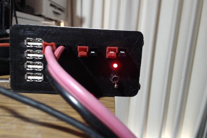
Here is the "final" setup for the R2Z-6400P-R power supply. And it works

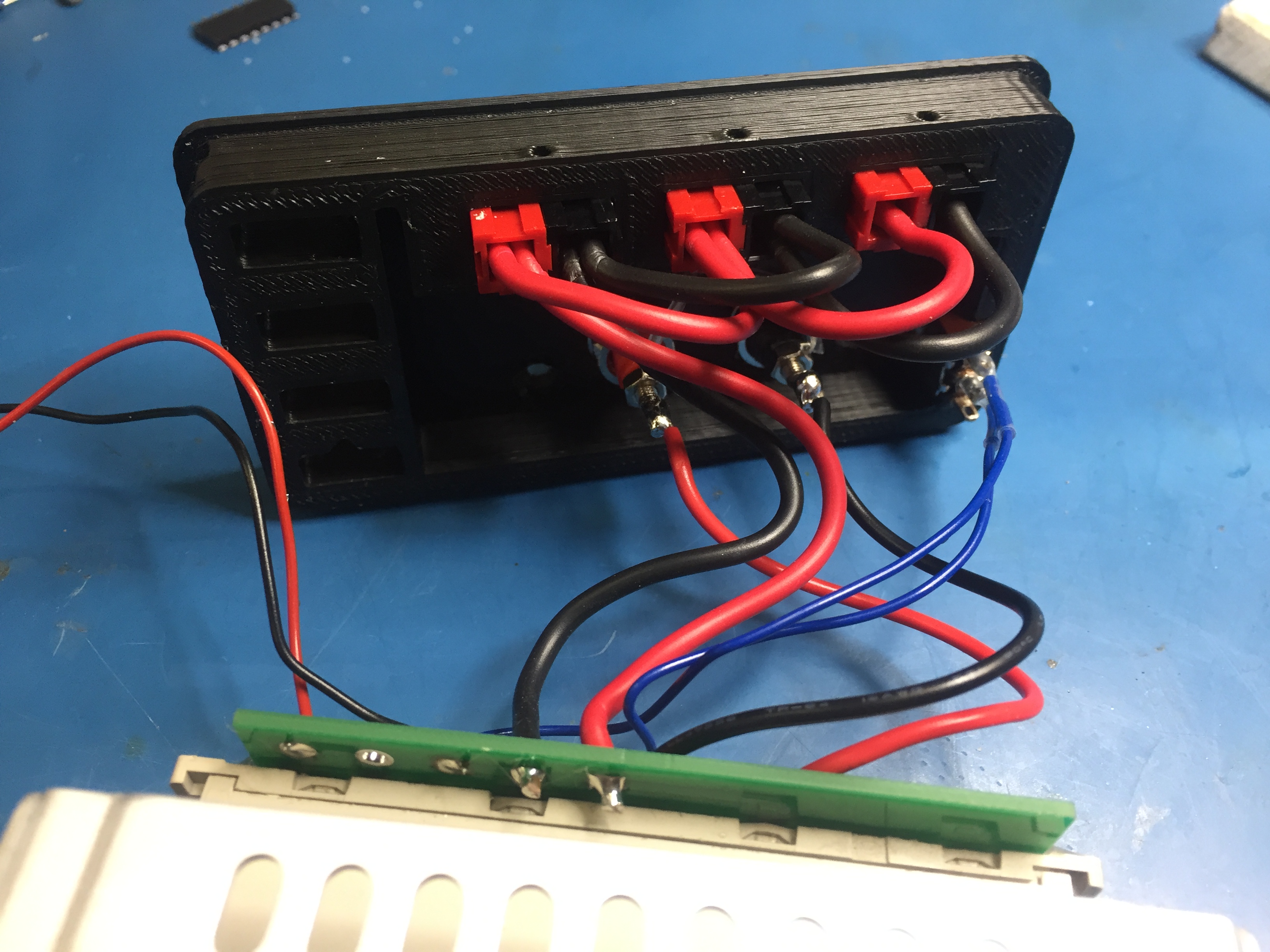
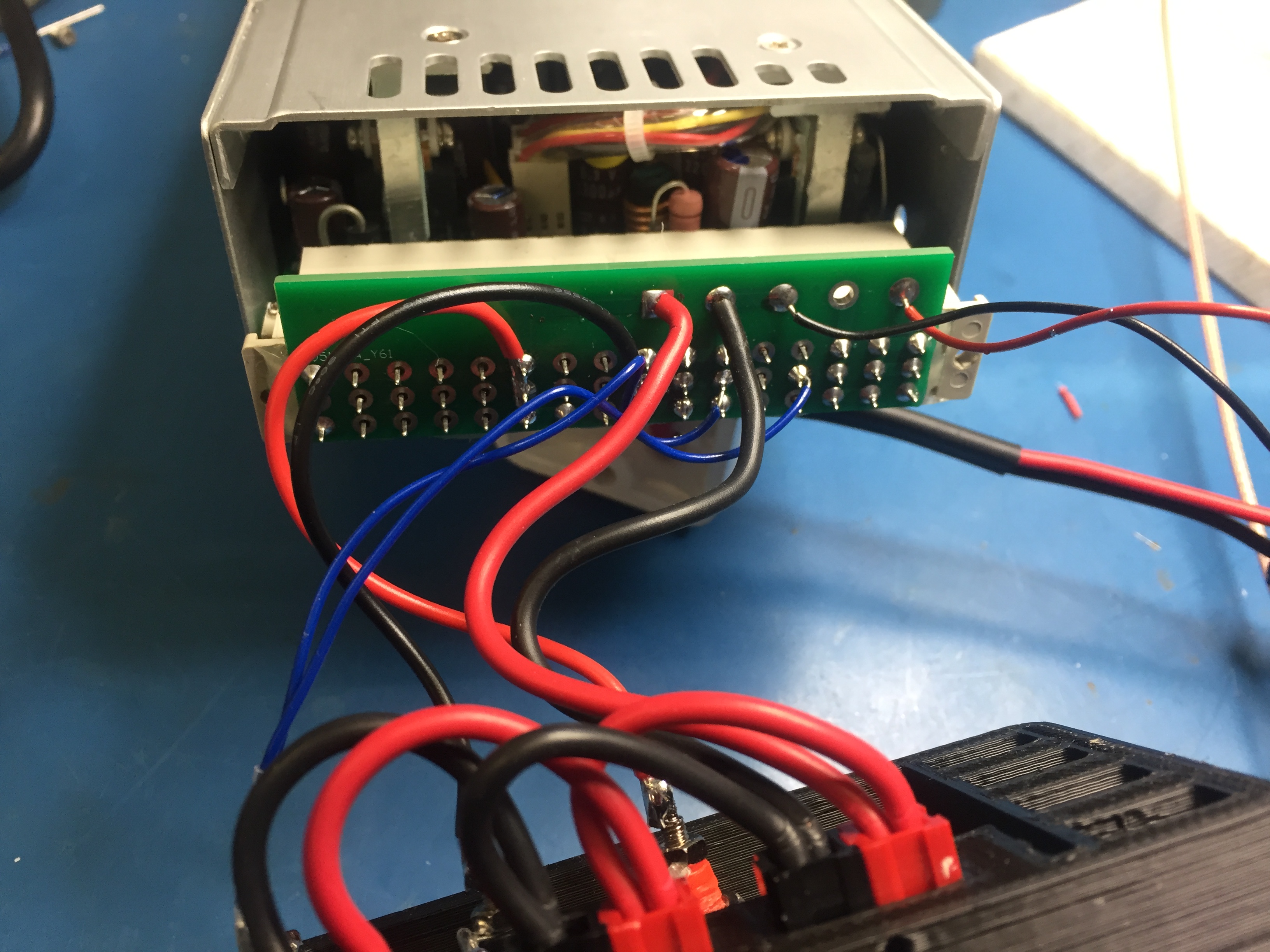
Front panel connections

5V to fans. It was 12V but then they are to loud.

Connections to the front.

Connections to the socket PCB.
I may add Polyswitches and programming resistors to the USB sockets, maybe
Front panel connections
5V to fans. It was 12V but then they are to loud.
Connections to the front.
Connections to the socket PCB.
I may add Polyswitches and programming resistors to the USB sockets, maybe
Last edited:
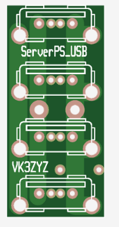
https://www.thingiverse.com/thing:6139326 has the .stl files if you want to build one yourself.
The adaptor PCB's arrived, so there should be a few finished by the time of the hamfest. I need to redo the USB connectors, and figure out why I couldn't plug into them after assembly. I suspect that the pins moved when I soldered the connections, so it might be necessary to have a male connector plugged in while soldering the connections.