V
VK3ZYZ
Guest
On snooping in a second hand shop, I spotted a lonely looking HF transceiver priced at $60, marked down to $30. Not too bad for a 100W SSB set!
EDIT: I think it may be 25Watts.
This started my exploration of HF.
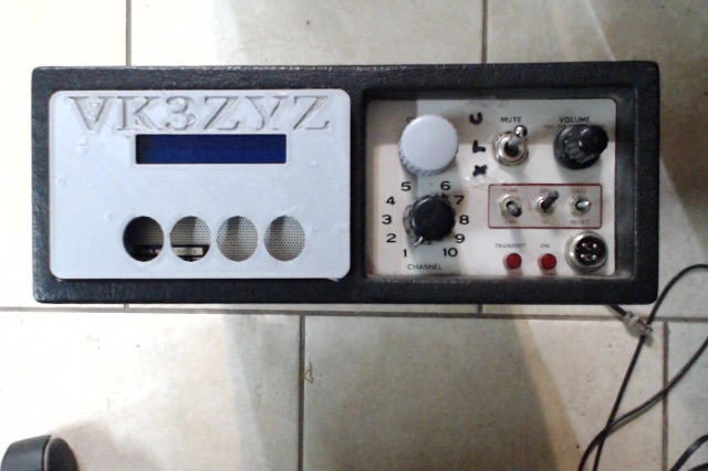
This is the first Arduino VFO I did. It ended up looking like this.
This set was only fitted with 2 channels so more coils are needed to add more bands. As yet, I do not have them.
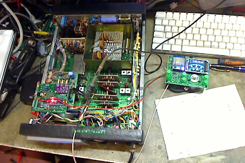
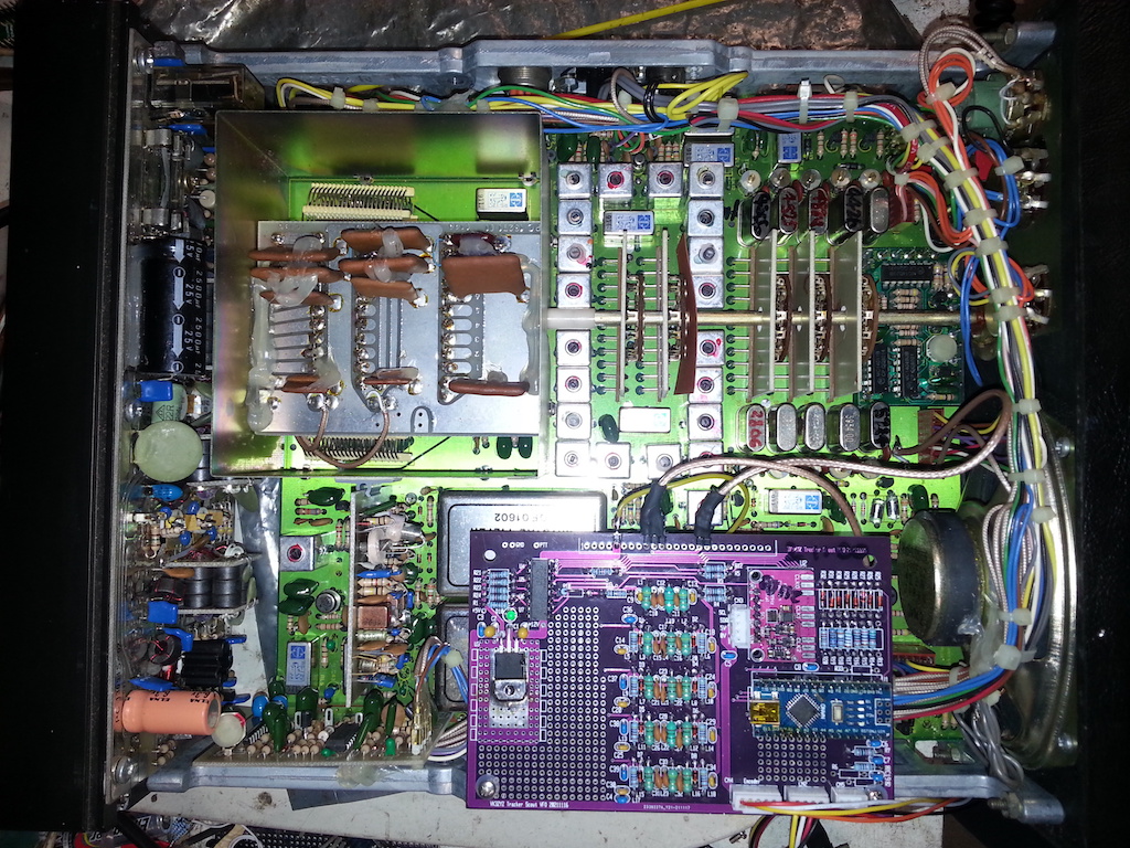
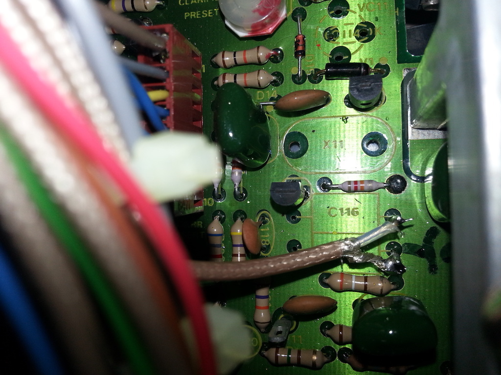
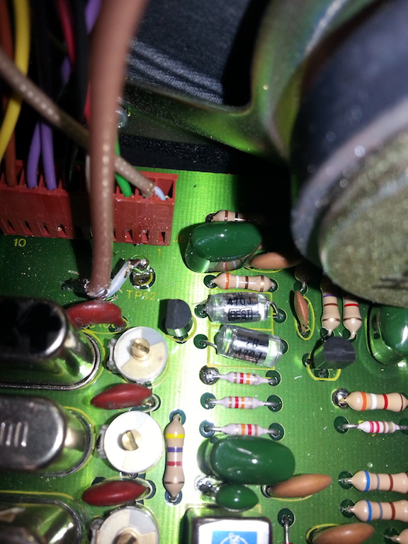
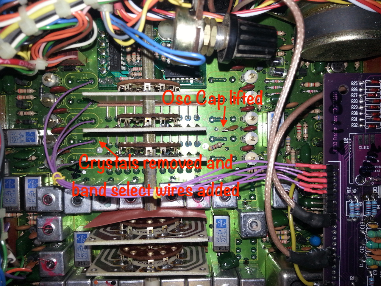
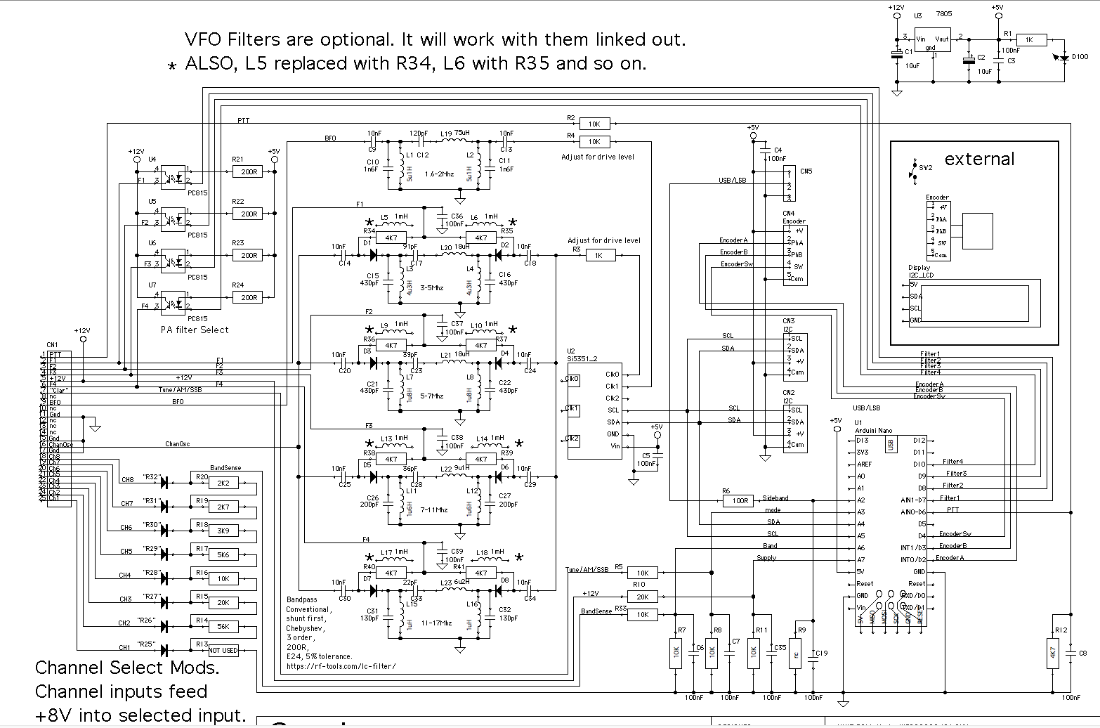
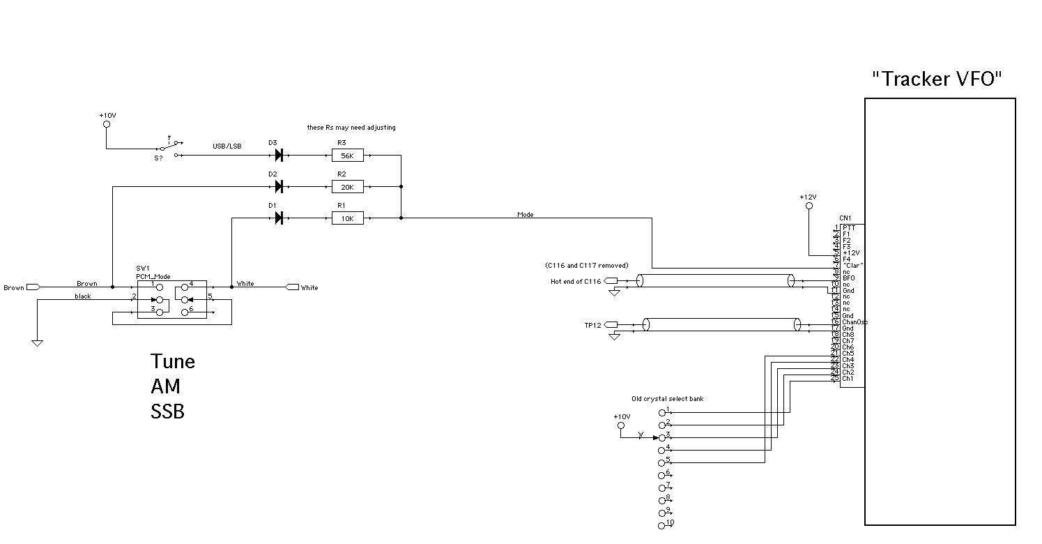
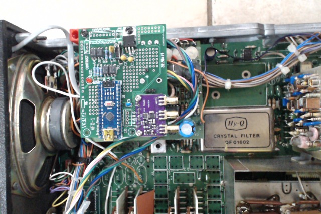
After discovering the Si5351 tripple VFO board, and playing with that for a bit, I decided to start the conversion. The crystals have been removed and the PCB I drew up a to hold an Arduino Nano and the Si5351 VFO board is mounted on a 3D printed spacer screwed to the side frame.
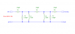
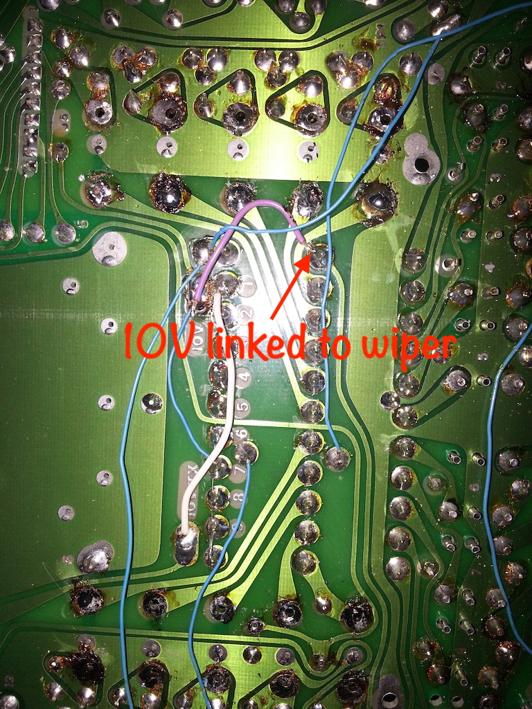
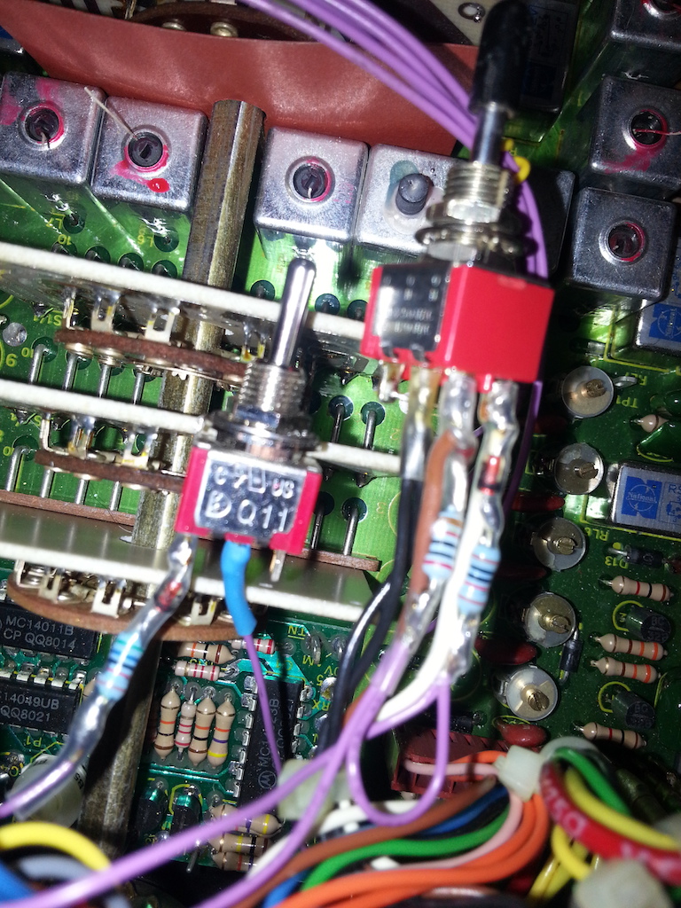
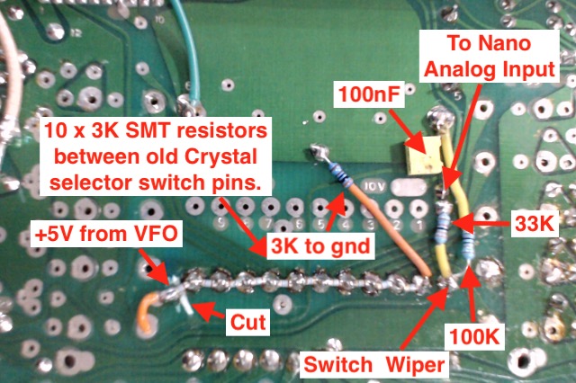
A string of resistors fit nicely between the old crystal switch terminals to produce a resistive divider that feeds a stepped voltage to the Arduino so it knows what band is selected. The PCB has a couple of cuts to suit.
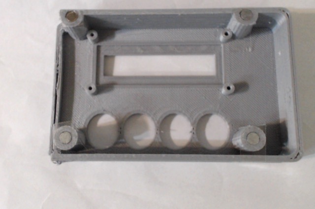
As I did not want to cut large holes in the front, a 3D printed display box fits over the speaker and is held in by magnets. Just a small hole is needed to feed the 4 wires out to drive the I2C LCD.
The above is a quick introduction to this project.
Here below is a bit more detail, a pdf of the build, some Arduino code and the service manual.
And the info of #1 VFO.
This set is calling out for the Adaptive VFO talked about elsewhere in this forum.
EDIT: I think it may be 25Watts.
This started my exploration of HF.
This is the first Arduino VFO I did. It ended up looking like this.
This set was only fitted with 2 channels so more coils are needed to add more bands. As yet, I do not have them.
After discovering the Si5351 tripple VFO board, and playing with that for a bit, I decided to start the conversion. The crystals have been removed and the PCB I drew up a to hold an Arduino Nano and the Si5351 VFO board is mounted on a 3D printed spacer screwed to the side frame.
A string of resistors fit nicely between the old crystal switch terminals to produce a resistive divider that feeds a stepped voltage to the Arduino so it knows what band is selected. The PCB has a couple of cuts to suit.
As I did not want to cut large holes in the front, a 3D printed display box fits over the speaker and is held in by magnets. Just a small hole is needed to feed the 4 wires out to drive the I2C LCD.
The above is a quick introduction to this project.
Here below is a bit more detail, a pdf of the build, some Arduino code and the service manual.
And the info of #1 VFO.
This set is calling out for the Adaptive VFO talked about elsewhere in this forum.
Attachments
-
6.6 MB Views: 810
-
5.3 KB Views: 697
-
2.3 MB Views: 782
-
89.4 KB Views: 690
-
1.1 MB Views: 748
Last edited by a moderator:
")