Solar inverter noise

VK3ZYZ

Moderator
Staff member
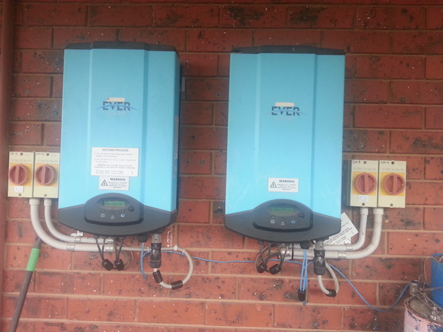
Ray and Josh came around here and had a little bit of a play to try and track down the noise from my solar inverters.
I've just fixed (I hope) the IC22S and put it back into service.
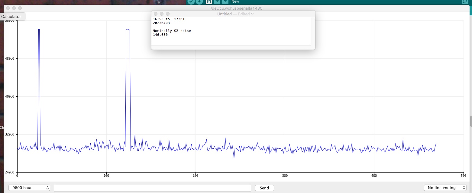
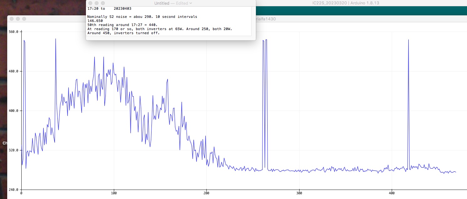
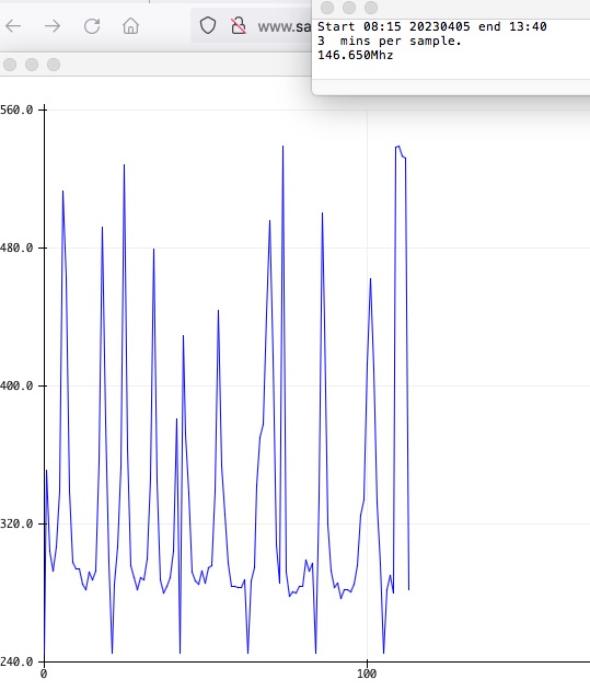
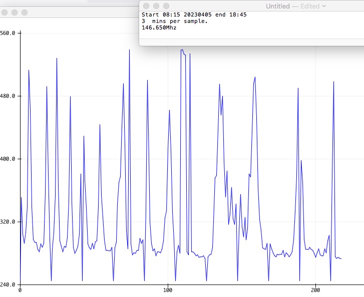
It has an S meter so the noise level can be monitored.
Here is the repeater at the moment..
Photo on 3-4-23 at 12.16 pm #2.jpg

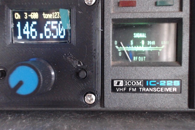
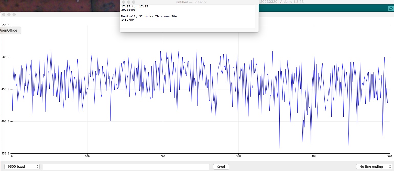
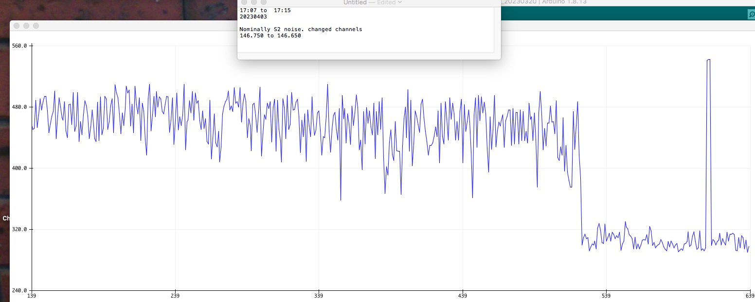
It is quite ok. But have a look at a little higher in the band...
Photo on 3-4-23 at 12.16 pm.jpg


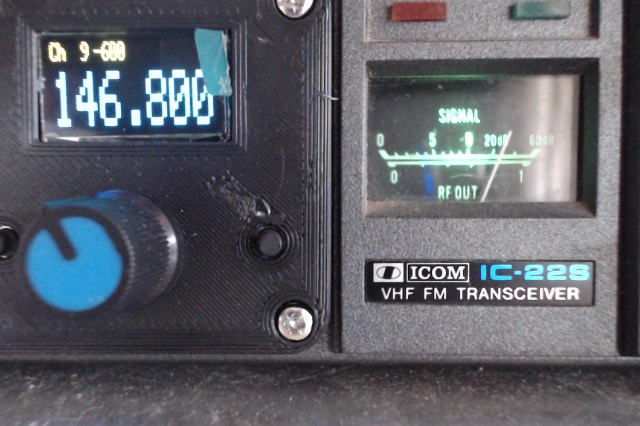
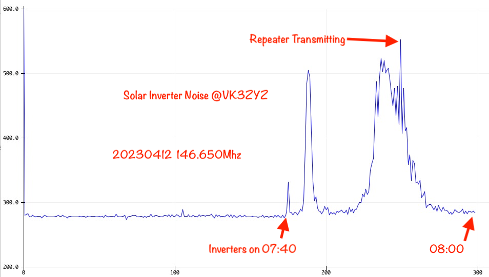
This interference frequency varies with the inverter power. At the moment, the inverters are running at 3.2KW and 2.8KW. It appears I have a crook panel or two as they should be about the same.
AHHHHH! The IC22S just dropped out of lock again so I did not fix it!
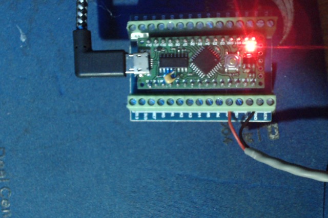
A mod I did was to extend the S meter signal out so I can organize to log it. And if the software was still working, there is a capability to read the inverters too but I do not know how to do that.

Back to the shed with the IC22S!!!!
 

VK3ZYZ

Moderator
Staff member
Inverters.jpg

Here are my inverters with the Ferrite clip-ons Ray installed. I've got to get the IC22S running again so the S meter can be used to see if adding Ferrite makes any difference.
 

VK3ZYZ

Moderator
Staff member
I've run a series of S meter tests.
Here is the code.
Code:
#define Version "IC22S_Smeter"

#define S_Meter A7    // S_Meter Input
int reading;
void setup() {
Serial.begin(9600);
}

void loop() {
  reading=(analogRead(S_Meter));
  Serial.println(reading);
  delay(10000);

}

S-MeterTest2.jpg

Around 5PM, this is the listening to the Mt Wombat 2M repeater. You can see when it is triggered. 1 sample per second.

S-MeterTest3.jpg

Here is the noise on 146.750 around the same time.


S-MeterTest4.jpg

Just to show the noise is on specific frequencies, depending on how the inverters are running, you can see the drop when changed from 146.750 to 146.650Mhz.

S-MeterTest5.jpg

And here it is on 146.650 towards the end of the day. The inverters finally shut down at around 450 mark. 1 sample every 10 seconds.
Photo on 3-4-23 at 6.54 pm.jpg


A good use of the Arduino Nano screw terminals!
 

VK3ZYZ

Moderator
Staff member
I've altered the code to read at 3 mins intervals so I can fit a full day into the 500 reading spaces.
Also, every hour, there is a pulse to mark the time.

Code:
#define Version "IC22S_Smeter"
#define S_Meter A7    // S_Meter Input
int reading;
int hour_counter= 0;
void setup() {
Serial.begin(9600);
Serial.println(245);    // mark hour
}
void loop() {
  reading=(analogRead(S_Meter));
  Serial.println(reading);
  hour_counter ++;
    if (hour_counter == 20)
  { Serial.println(245);    // mark hour
    hour_counter = 0;       // reset it.
  }
  delay(180000);  // 3 mins.
}
S-MeterTest7.jpg

Note, at the end of the graph, it shows me talking to VK3JRA. Hence the thick bar.
 
Last edited:

VK3ZYZ

Moderator
Staff member
Here is today's scan. The inverters have closed down. You can see how the interference changes during the day.
When the 36 Ferrite clip-ons get here, I'll load the leads up and see if the scan changes.

S-MeterTest8.jpg
 

VK3ZYZ

Moderator
Staff member
I was interested to catch the inverters starting up.
Here is a plot at 10 second sample intervals.
1681250904173.png
 

VK3ZYZ

Moderator
Staff member
Latest update. The clip on coils arrived so they are installed and no noticeable improvement has been notices.
I may try to get a good Earth to the inverters.
 

BillC

Active member
Pretty tough that inverter noise, can you track around with a sniffer to check for higher radiation zones etc , I am fairly sure if one needed a wide band noise source you would build an inverter. However it looks as though you have a nice data logging system there now Denys? . Cheers.
 
Top