Mt Wombat Power Supply Upgrade

VK3YNV

Administrator
Staff member
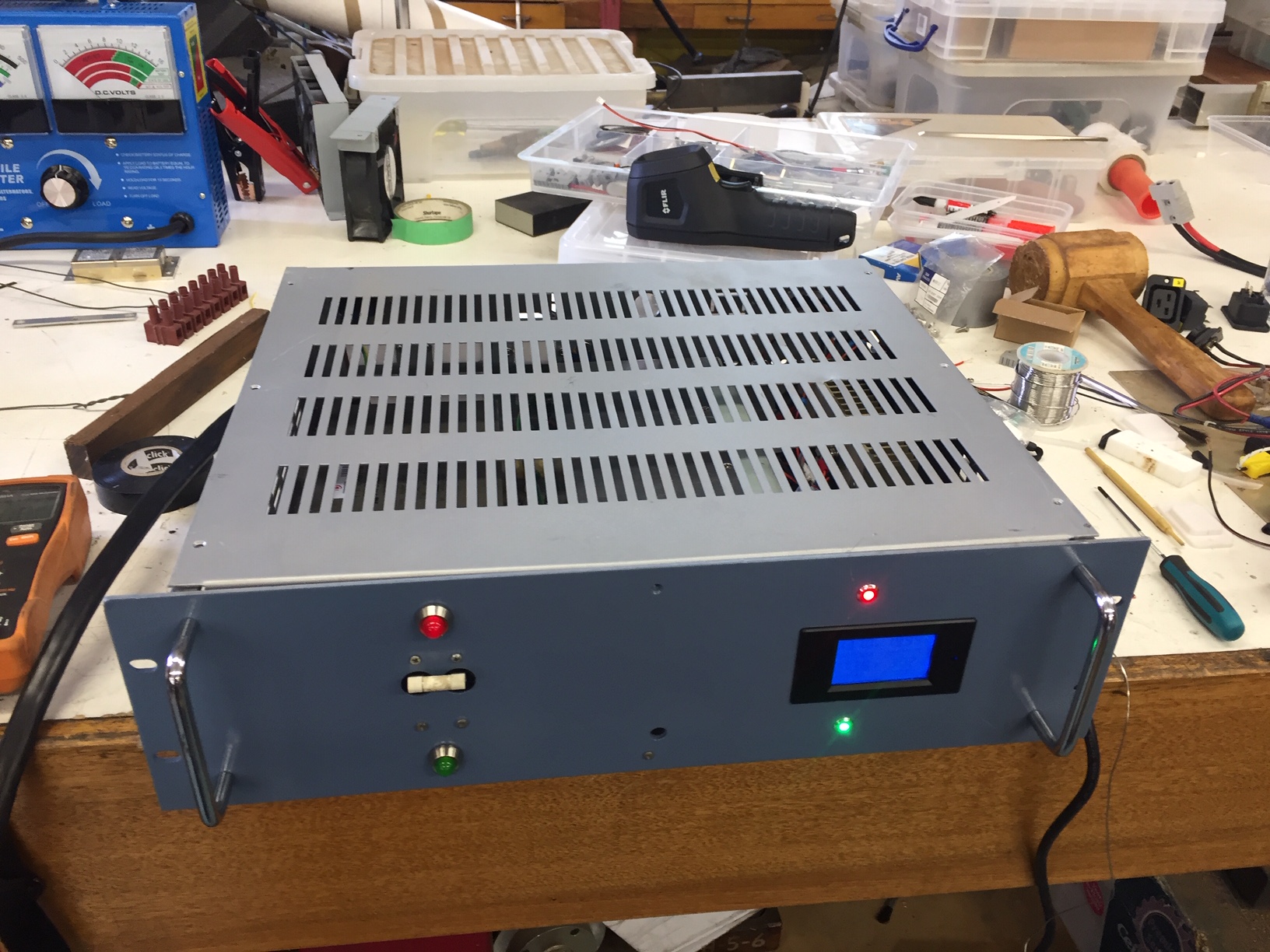
I've started testing the Mt Wombat PSU upgrade. This is intended to become the new main power supply, and the two 30A motorola units will revert to backup status.

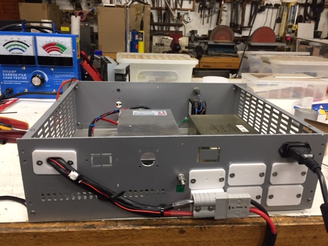
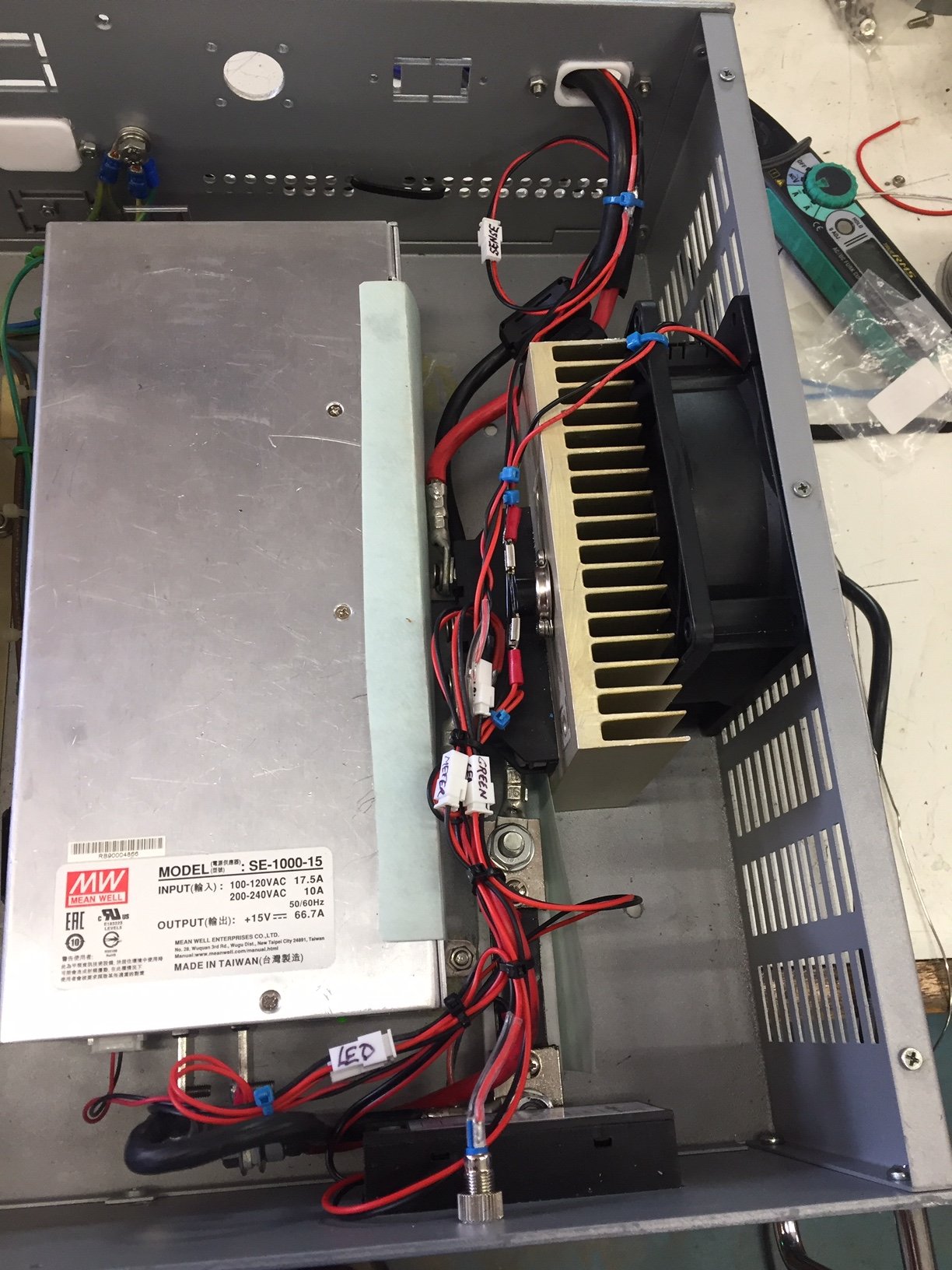
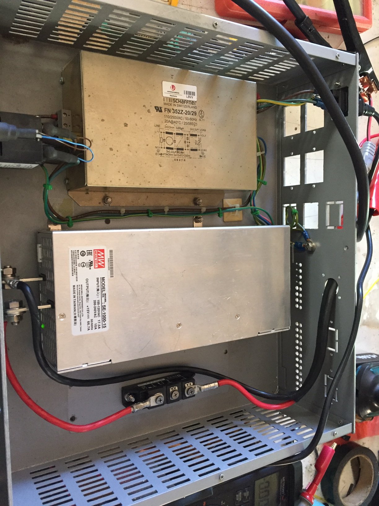
The PSU is built in a 3U rack with mains filter and a blocking diode on the output.

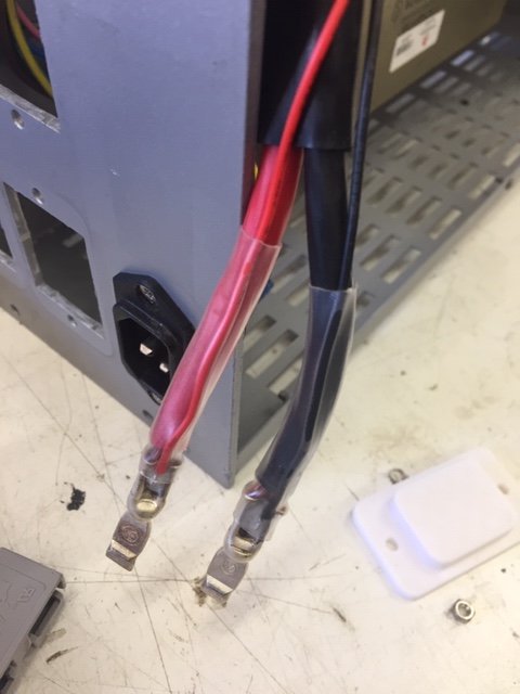
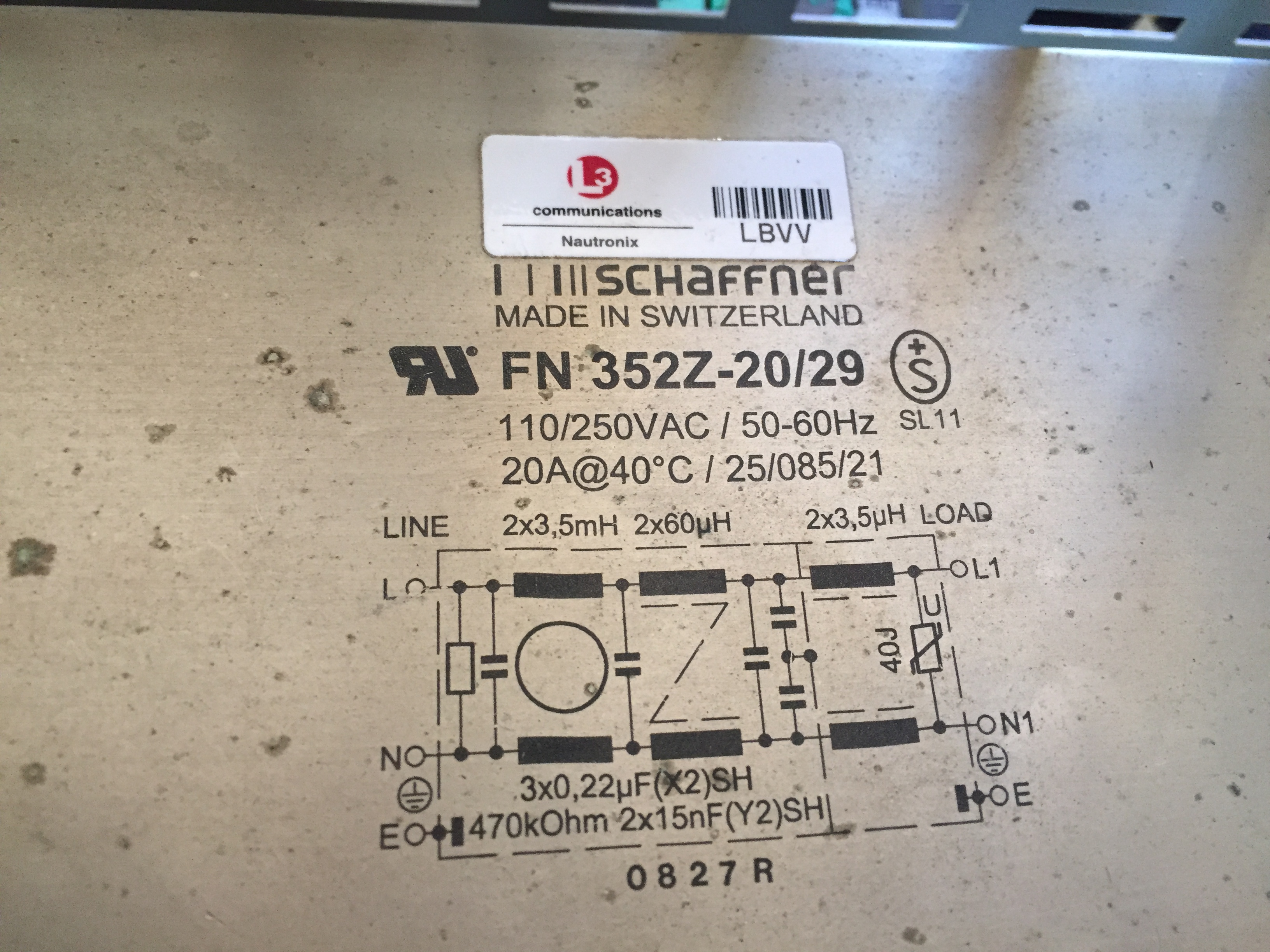
The mains input filter is a Schaffner
IMG_5670.JPG


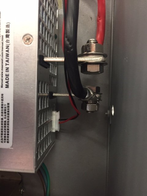
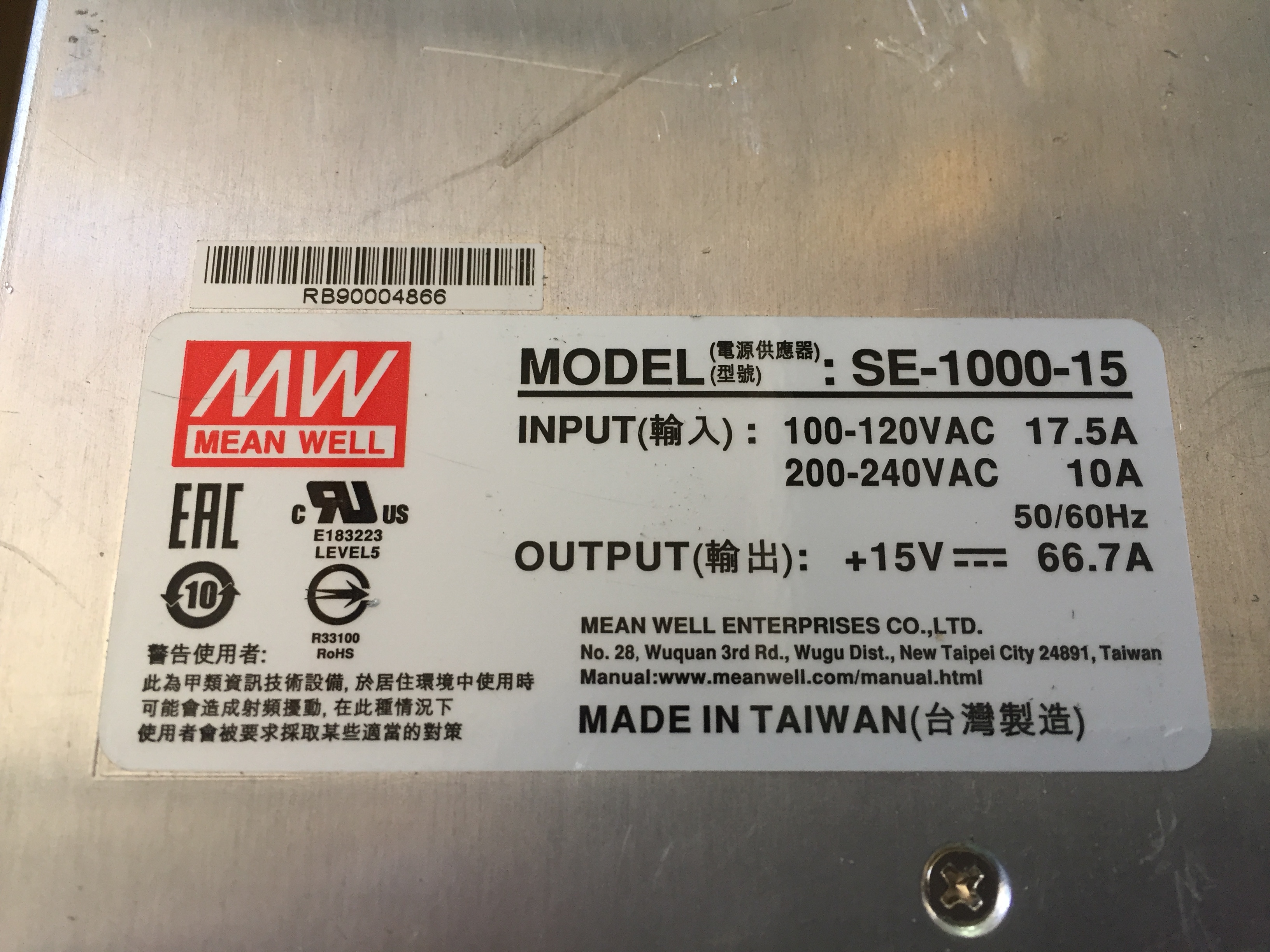
The power supply itself is a Meanwell

IMG_5669.JPG


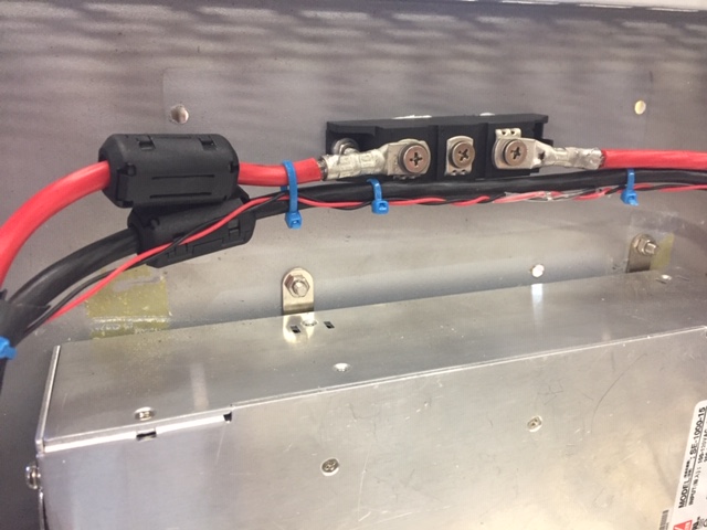
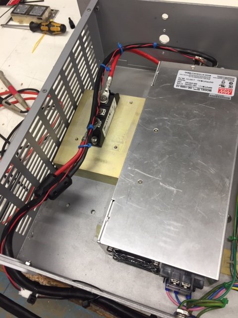
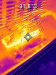
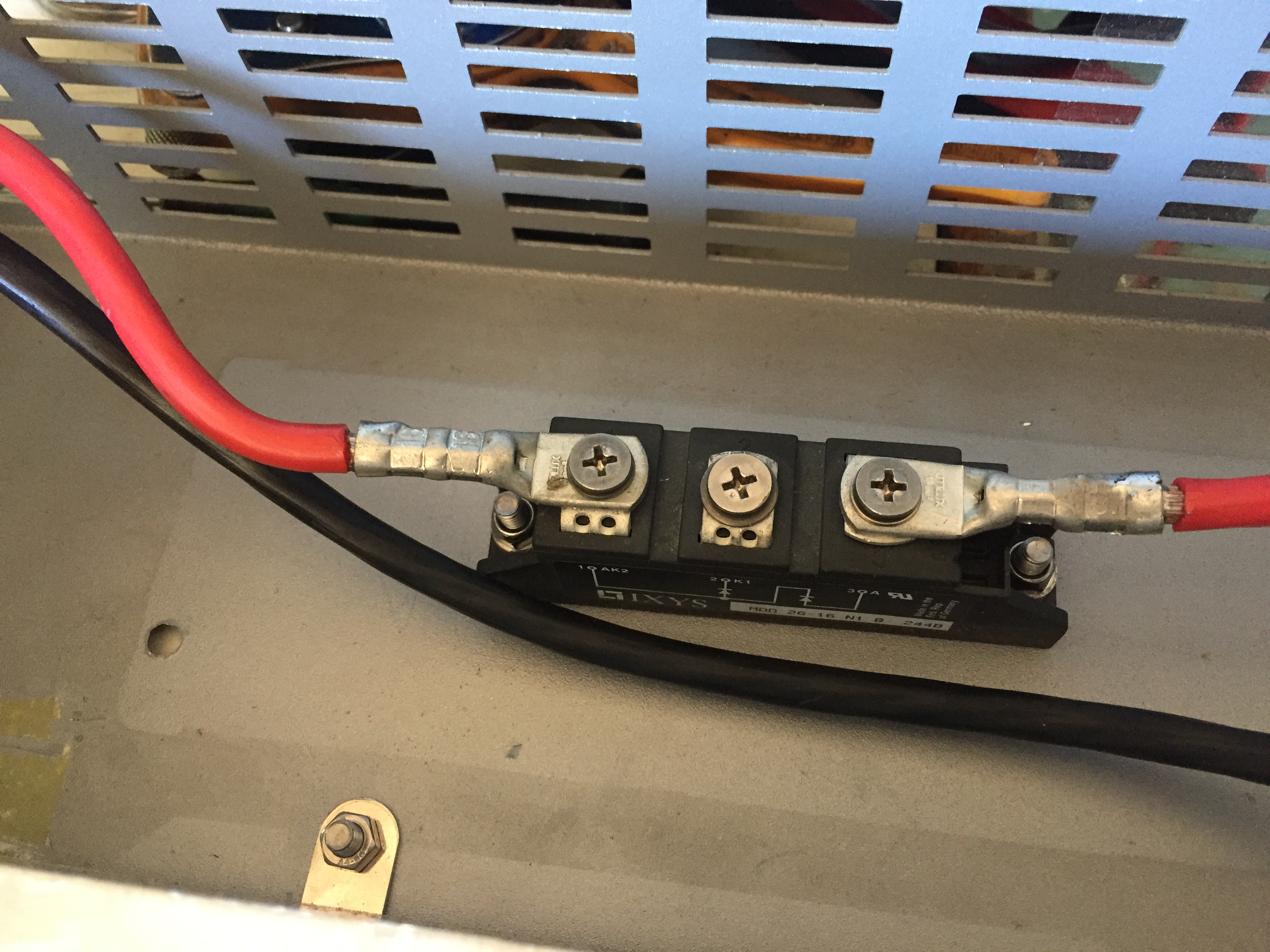
And the output diode is an IXYS Dual Diode Module 2x120A 1600V TO-240AA, we are only using one of the diodes in the pacjage.

IMG_5671.JPG


General arrangement within the enclosure.
IMG_5666.JPG


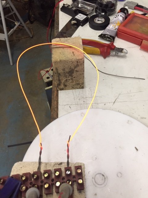
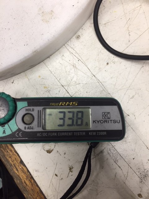
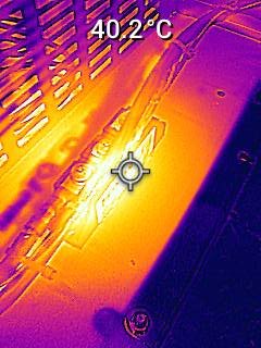
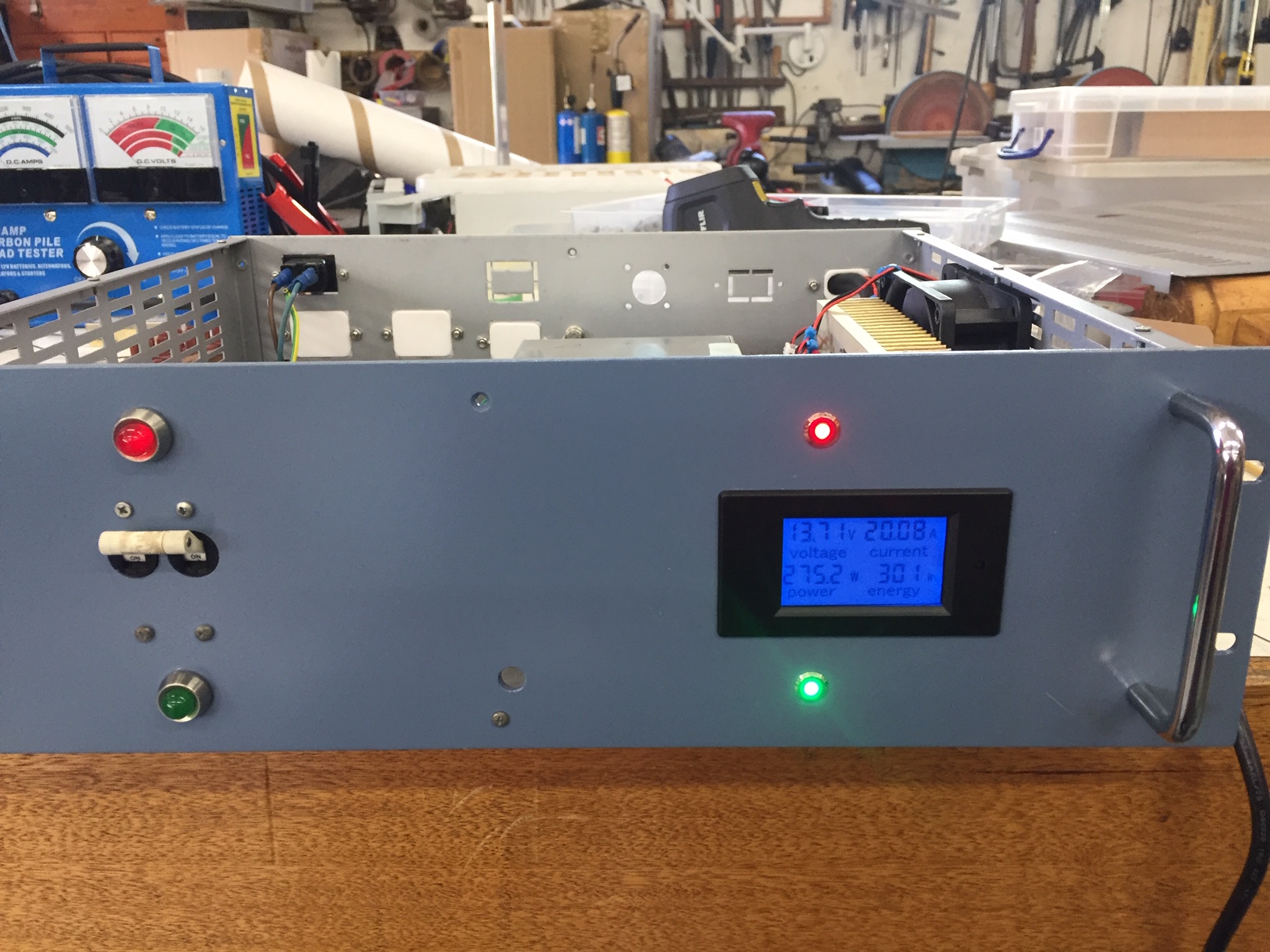
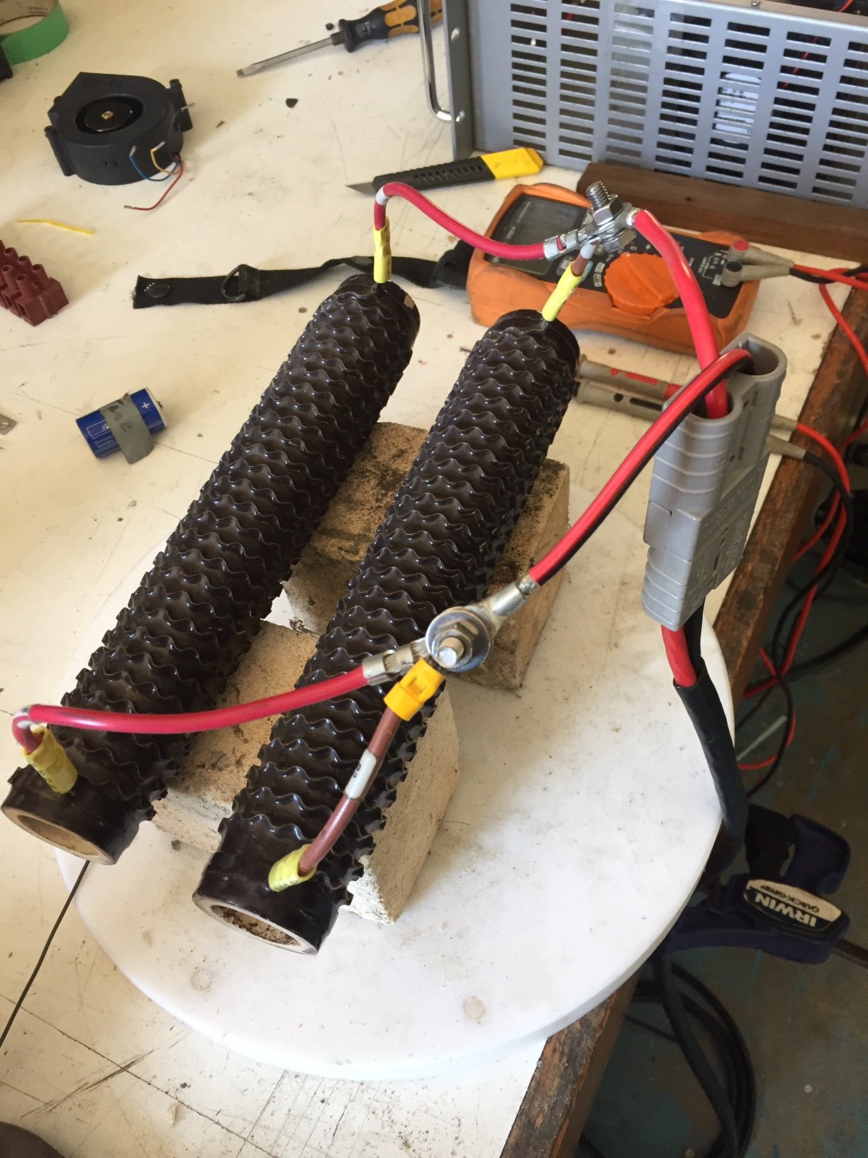
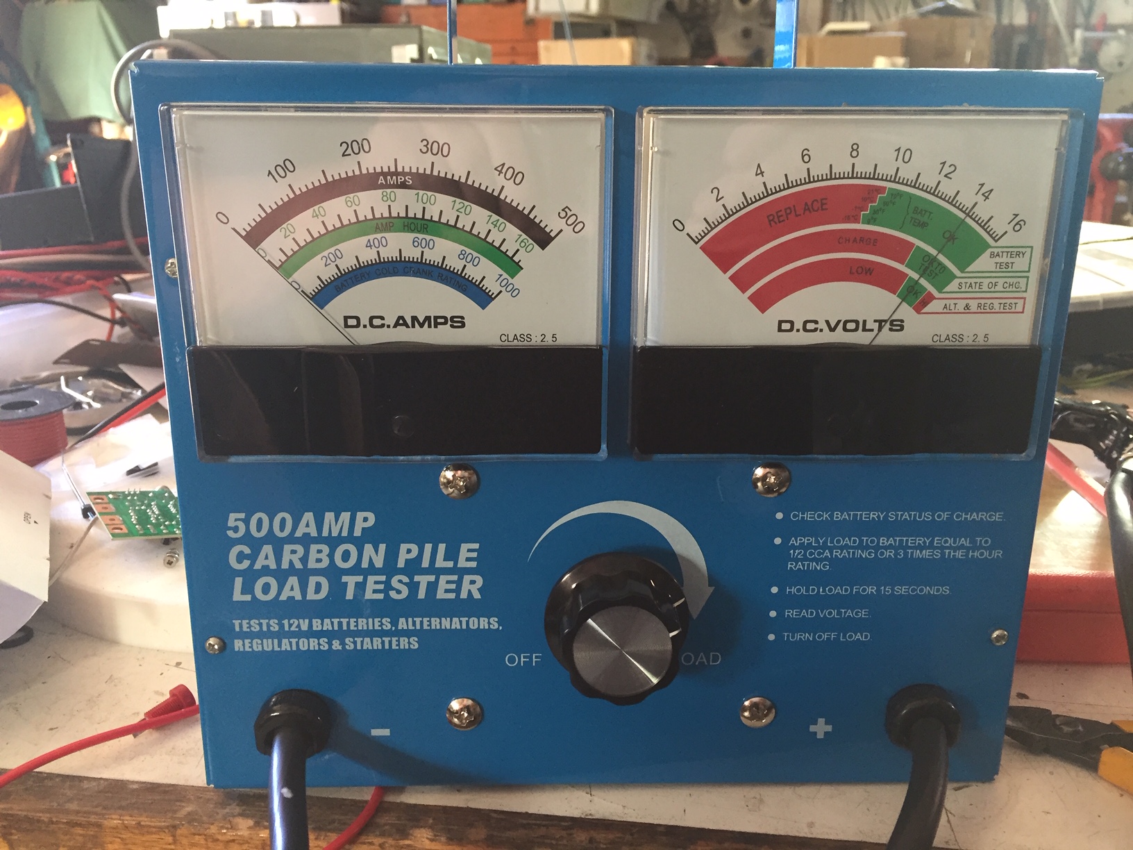
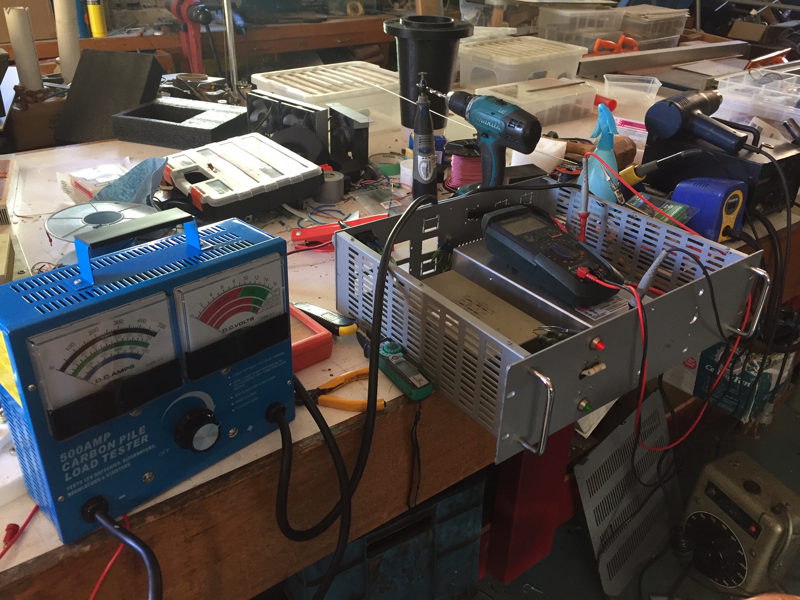
For testing I am using a carbon pile load, with the internal timer removed. It's rated at 500A for a few seconds. I'm currently testing at 50A, but the carbon pile soon warms up.
IMG_5668.JPG


Time to start cleaning up the workbench.

IMG_5665.JPG
 

VK3YNV

Administrator
Staff member
Getting closer to wrapping this one up.

The Meanwell PSU has the ability to use remote sensing, so that can be used to cancel out the diode voltage drop as the load varies, so as to maintain 13.7-13.8 volts at the Anderson Connector.

IMG_5674.JPG
IMG_5673.JPG
IMG_5672.JPG


The back panel was cleaned up with some 3D printed blanking plugs.

IMG_5676.JPG


The load for long term thermal testing is a nichrome wire that draws about 30-35 Amps at 13.7V
IMG_5692.JPG

It's resting on some high temperature fire bricks.
IMG_5690.JPG

IMG_5682.JPG


The FLIR TG267, showed the diode running about 50-60C, which is too hot. So the diode has been remounted on a heatsink, and I'll find a suitable fan with a thermostat switch

Before heatsink
FLIR1000025.jpeg

After Heatsink

FLIR1000029.jpeg


IMG_5688.JPG

So far I'm pretty happy with the Meanwell PSU, it's a good quality unit that I hope will give us many years of trouble free
power on Mt Wombat for all of the club repeaters.

Ray
VK3YNV
 

Attachments

VK3YNV

Administrator
Staff member
I dug out a couple of 500 Watt 1.3 ohm resistors, for a long term soak test, That gives ~20A or so.
Other final touches are a temperature controlled fan on the Diode heasink, and a meter on the front panel.


IMG_5703.JPG


IMG_5702.JPG

IMG_5701.JPG


IMG_5699.JPG


The plan is to run it at 20A for a few hours and then see what the temperatures look like.
 

VK3YNV

Administrator
Staff member
Soak test results after a few hours.
Nothing much happening at 20A, diode heatsink settled down at 44-45 degrees C.

So to keep Dallas happy I went back to the nichrome wire and 40A load. That was sufficient for the colling fan to kick in and the temperature has stabilized at 41-42 degrees C.

That was a bit unexpected, it runs cooler at 40A than it did at 20A. ( Only because the fan kicked in )

Didn't do much to heat the workshop however.

Ambient is around 20C for these tests.
 
Top