Converting a Solar Lead Acid GEL battery system to Lithium

VK2RK

Active member
Importing and commissioning Lithium presents several problems that will send you down the rabbit hole, in the end the cost saving is huge offsetting the pain experienced making it worthwhile.

IMAG1782-20200225-103618539.jpg
IMAG1783-20200225-103638802.jpg
IMAG1787-20200225-103721390.jpg

Old Lead acid system 800 Ah at 48 Volts art 50% discharge useable 19.2 KWh

IMAG4461.jpg

Lithium system providing 21.4 KWh

Pack0Parameters .jpg


Conversion from Lead Acid to Lithium
At first the conversion seemed straight forward as the Inverter/Charger does provide for either managed Lithium or self-managed Lithium.
little did I know I was about to go down the rabbit hole.

Full Article
 

Attachments

VK3YNV

Administrator
Staff member
Nice work, the top balancing issue is one that I would have missed. But obvious in retrospect.

Interesting read. Thanks
 

VK2RK

Active member
Nice work, the top balancing issue is one that I would have missed. But obvious in retrospect.

Interesting read. Thanks
At first the whole thing had me tossed, I had no idea why the system was shutting down and Selectronic was not of any real help but to lower the charge voltage. In general it was one large stuff-up with issues from charging to communicating with the packs.
Faulty cables from the manufacturer (4 of them ) wired wrong, that had me going, I should have known better from China
Again it was worth the pain as the dollar saving was huge.
 

VK2RK

Active member
As an update, after just over a week having configured the BMS's to not shutdown due to cell overvoltage allowing the cells to balance to each other, the result is that those cells that rose above 3.7 volts are no longer doing so remaining within 20 mV of all other cells.
The BMS's parameters have now been returned to factory settings.
Happy camper I am.
 

VK3ELV

New member
I finally got around to finishing mine around last August. I will see if I can get a picture. My cells were unused 2nd hand from 2016 ( electric bus batteries) and I had all the cells paralleled for about 12 months to try and pre-balance them. It sounds like you also have a Selectronic inverter they are very flexible. I have a BMS setup for 16 X 3.2 volts but if a cell fails or 2 weaker ones need to be paralleled, I can set it up as 15 X 3.2 volts. The top balancing current of my BMS is a bit limited so the first couple of charge cycles I had to manually intervene by discharging some cells a little with 12 volt light globes and reduce the maximum charge voltage from the SP Pro charger/inverter.
specs.jpg
 

VK2RK

Active member
Some pics of my system
Nice to see others getting involved in properly built battery systems, with lithium as you know the BMS is the secret to good safe performance, there is a degree of understanding required to handle these batteries and add to that the capabilities of the BMS.
Not sure what kind of BMS you are using, there is so many on the market today, the most important part is the reliability of these units, their role aside the safety part is to keep cells balanced, as you know this is done using shunt devices to lower the cell voltage, so the hard work done and heat generated is due to this balancing process.

With the Selectronic as you say a very flexible unit you can set parameters to obtain the best performance from the battery system, one bit of advice I can give you to prolong the battery life is to set the maximum charge voltage below the top voltage, taking lithium to the top of charge voltage does reduce their cycle life, the energy loss is minimal if you look at a Lipo graph the difference is very small. In my case using prismatic cells I have my top of charge voltage set at 56 V (3.5V cell) If you can get a graph for the cells you are using then decide the best point for your application, I also do not discharge past 20 % SOC

Here are my battery packs specifications as a guide for you.

Pack Spec..jpg
 
Last edited:

VK3ELV

New member
My BMS is a ZEVA, originally designed for EV conversions. and was designed in Perth WA but he closed shop about 12 months ago. I was even more conservative with my top voltage set a 55 volts. I used to own a Gen 1 Nissan LEAF, so I know about battery degradation ( Hi Hi ).
I found this little chart handy as it is a lot quicker and easier to read than a lot of the graphs.
 

Attachments

VK2RK

Active member
The BMS used in my packs are made by PACE, they do offer the parameters management that if properly configured will look after the cells, excluding BMS faults, fingers crossed, having said this, no bad reports that I was able to find.

I tend to look at more comprehensive battery specifications to decide upon the best parameters to achieve the greatest number of cycles, the problem with Chinese sourced batteries none provide detailed cell specifications but only provide pack settings that are preprogramed in the BMS.

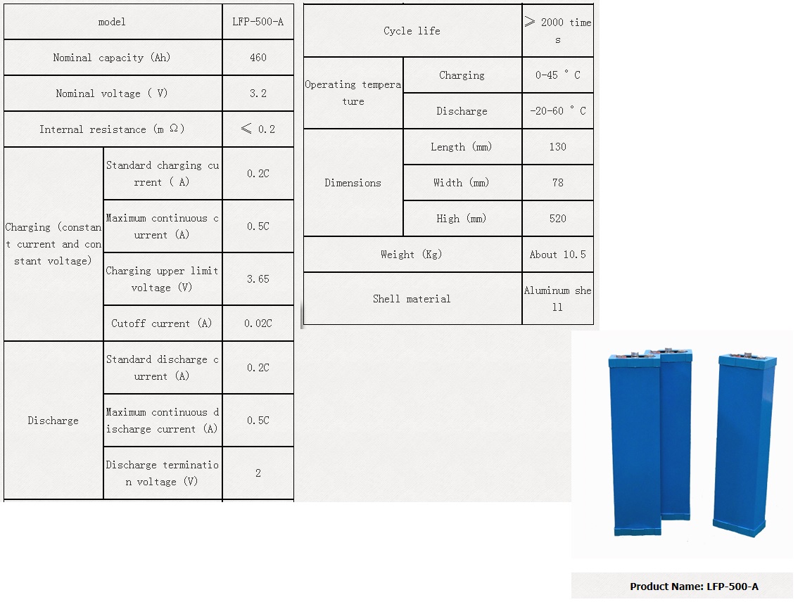
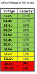
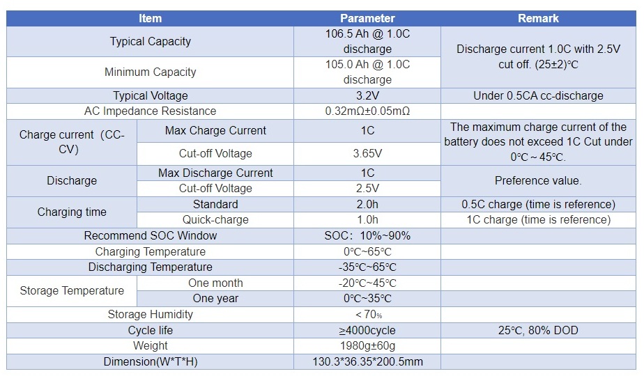
I found detailed cell specifications that are very similar to what I have, from these specification I noted that the cell manufacturer recommends a SOC cycling of 10% to 90% with a cut-off voltage of 3.65 volts. I can easily establish the best top end voltage of 3.285 volts based on the 90%
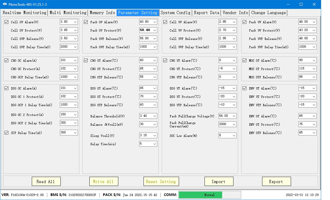
This seems to be too low. I went back to the pack manufacturer by looking at the BMS settings, they specify in the manual a max voltage of 3.55 Volts
The cut off is set at this level and the pack disconnect from the charger.
By looking at the data sheet and the instruction book data the charge voltage is 97% Note that they claim 6000 cycles whilst the battery datasheet claims 4000 cycles.

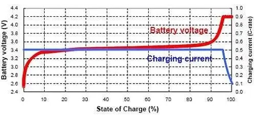
In my research I found there is a direct relationship from the number of cycles to the value of top charge voltage used, the lower the less heat and the longest number of cycles.

With the above information I went to the actual graph for LiFePO and noted that the energy stored as a function of voltage
Untitled.jpg

Between 3.6 and 3.8 there is little to be gained as stored energy, noting that the pack manufacturer is already operating below 3.6 Volts at 3.55 Volts, clearly to achieve the stated number of cycles.
I chose 3.52 Volts, doing so from recommendation of others with more knowledge than I on using Chines packs.

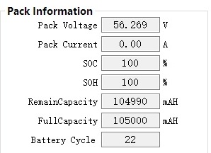
Table from BMS showing less than -1% of SOC (Note BMS has tuned off the pack when fully charged and the house load is on the solar panels)
BMS.jpg


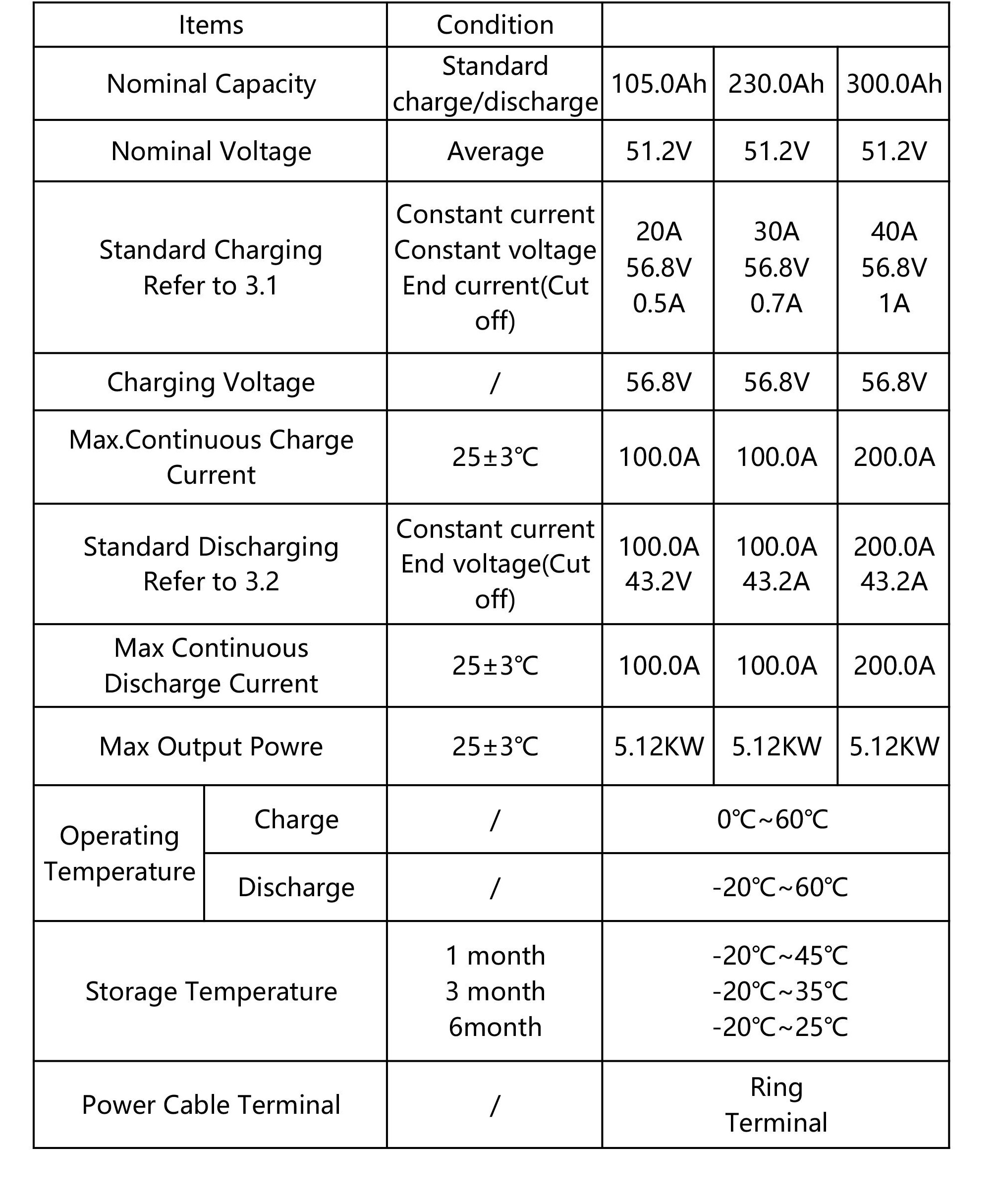
Reference data from similar cell used in my system.
Prismatic.jpg


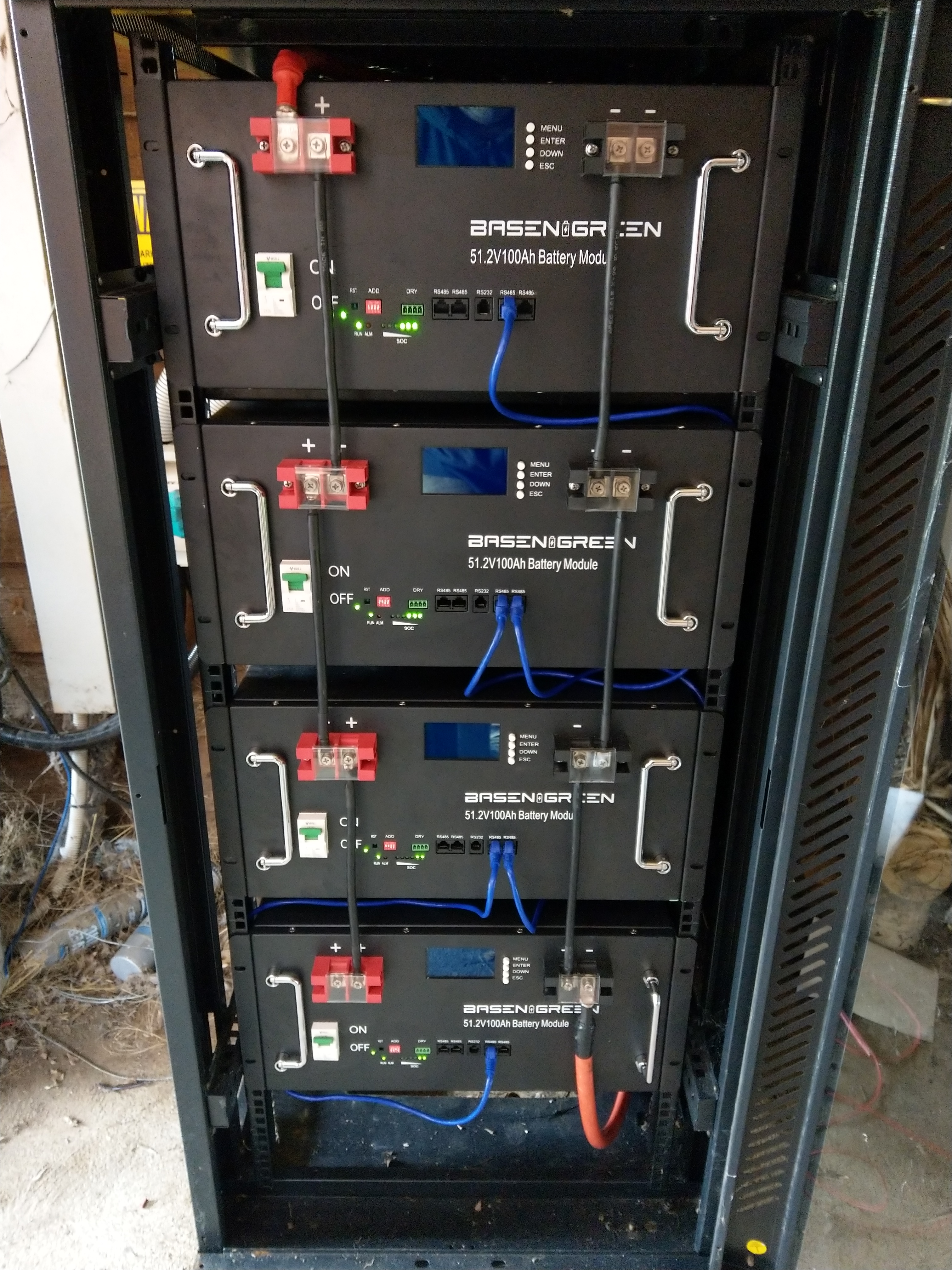
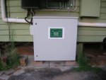
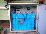
In the design I was conscious if using 400 Ah system of the large cycling currents, then if a failure in a cell was to take place the whole system would be off line, so I chose four 105 Ah packs to provide redundancy and lowering the currents involved on each pack and the associated temperature raises.
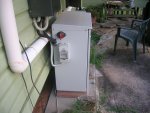
The BMS's communicate with each other via the CAN bus, I am noting that smart cycling is taking place to maintain pack to pack balance,
The average currents involved are very low the worst case I have logged is 20 Amps in each pack during a charge cycle, with 24 Amps during a full load discharge test, with this strategy the heat generated is kept at the lowest level possible.
 
Last edited:

VK2RK

Active member
New system ROI performance.

These are my results for the Quarter Dec to Feb 2022 expressed as Return on investment.
Net Dollar Return $281.92
Electricity Used Value $624.74
ROI $906.66 ( excludes service charge )

If I did not have the solar plant it would have cost me $906.66 plus service charge of $129.46 for quarter a total of $1036.12
Instead the system has paid me $281.92 net in my bank with ZERO to pay the supplier.

The GEL batteries gave similar results with a slightly lower efficiency due to the way Lead/Acid not fully switching off when fully charged.
 
Last edited:
Top