Codan 8727 info (And 7727)

V

VK3ZYZ

Guest
Does anyone have a service manual or even just a circuit for a Codan 8727 set?
I am getting one of these going again. It had broken switches on the front, and I have changed the mic connection to a 4 pin "standard", not the Codan 7 pin version.
After I get it working again, the next step will be to change to the VFO in place of the crystals.
I will post more info of the progress as it goes on.
 
V

VK3ZNA

Guest
Does anyone have a service manual or even just a circuit for a Codan 8727 set?
I am getting one of these going again. It had broken switches on the front, and I have changed the mic connection to a 4 pin "standard", not the Codan 7 pin version.
After I get it working again, the next step will be to change to the VFO in place of the crystals.
I will post more info of the progress as it goes on.
The Codan 8727 is a crystal locked version of the Codan 8528 radio.
Geoff VK3ZNA
 
V

VK3ZYZ

Guest
Codan8727_TestVFO_01.jpg

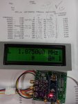
I am still battling with this one, but here is the set with the test VFO running it.
No mic TX yet, but otherwise ok.
 
V

VK3ZYZ

Guest
The receiver ran very well on tonight's 80M sked. And I actually did a tx test with whatever managed to squeeze through and it worked but quite distorted and very low power. When switching to Tune, it outputs plenty of power.
I am still baffled as to what is stopping the tx running with the mic.
 
B

BillC

Guest
There might be a polarity protection link or strap to re - configure ?
 
B

BillC

Guest
Also if there is a Tx / Rx c/o relay there might be diode in series with the PTT, a polarity protection diode in that position could protect the whole Tx stage from reverse polarity, if the diode was OC there would be no PTT function .??
 
V

VK3ZYZ

Guest
I have put some code into an Arduino VFO and am in the process of growing it into the Codan 8727.
Codan8727BandSelect2.jpg
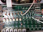
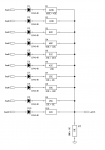
A resistive network is connected to the band switch and now selects the band on the Arduino.

Codan8727BandSelect1.jpg
This also shows the coax feeding the VFO in.
Later, I will clean all this up, but for now, it is just a quick test setup.

I'm pleased that my spreadsheet worked out well.
A few of the values had to be made from a couple of resistors as I did not have them but I think they are all standard 1% resistor values anyway.
BandResistors.png
BandResistorsODS.png
 

Attachments

V

VK3ZYZ

Guest
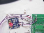
The 8727 now has the OLED display installed (on a slant).
The code below will compile for OLED or LCD as desired.
For a 2x16 LCD, change the line....

// comment out line below for LCD
#define USE_OLED
to
// comment out line below for LCD
// #define USE_OLED

Now that this code is working well, I may start on the 7727 set and see if I can make that one transmit correctly.

Front20210725_01.jpg

The red film is matt, and it would be better to just be clear red.
OLED_Matt_film.jpg
 

Attachments

Last edited by a moderator:
V

VK3ZYZ

Guest
The other radios from Doug have arrived.
I swapped the 08-03459 board out with another and the radio works now.
So, there is a problem with the original.
The red film removed from the display makes it easier to see.
WhiteOLED.jpg

And adding connectors to the 08-03459 board will let me swap them around so I can fix it.
08-03459_connections.jpg

This one does not have the 1.650/1.647Mhz coax on in place of the crystal as yet.

I had a talk with VK3GSR on it. The audio is still neot the best, but the power is more that the PCM Hawk.
There is still more work to do but it is getting there!
 
Last edited by a moderator:
V

VK3ZYZ

Guest
Here is the circuit of the VFO.
8727ArduinoSynth.png

I have added a band "override" TUNE input so the VFO can run from 1Mhz to 20Mhz on any band for tuning setup.
Here is the code.

It would not work on 7Mhz and that turned out to be a solder bridge that was shorting 2 of the Codan's band filters together.
Better now :)
 

Attachments

Last edited by a moderator:
V

VK3ZYZ

Guest
CODAN_7727_VFO_01.jpg

Here is the 7727 main board.
The crystals are removed.
Here is the Si5351 VFO in place.
 
Last edited by a moderator:
B

BillC

Guest
Nice job, I can't see where the Arduino controller is mounted.
 
V

VK3ZYZ

Guest
The 7727 is coming along.
CaseFront.jpg

Here is the front. I will use the remote socket hole for the OLED display and the encoder (blue knob) is in a hole that was there.
The grey knob is the volume control.
To the left are 3 push buttons that will be USB/LSB, Band Up and Band Down.
The switches to the right are power and mute.

I'm in the process of printing a mount for the OLED display and the Arduino synth board.

Synth_DisplayPlate.jpg

This is a rough print.

The OLED display will mount inside the printed part, and then the synth board mounts on the back of the printed part.

SynthMount.jpg

Like this.

Then, it will screw into the front using the existing old remote socket holes.
The final will be in black plastic, or at least painted black.

Then, the switches, encoder and the Si5351 board will be connected to it.
 
V

VK3ZYZ

Guest
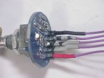
The encoder is a lot easier to wire as it has a PCB.
Encoder.JPG
This one looks to have a bit of crud in the push button as it took some CRC to get it working.
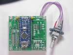
Then, it connects to the PCB
Encoder_Board.JPG
Next, the OLED display.
OLED_Board.JPG

And this is how it looks.

InPlace.jpg


I have some code funnies :(
And still wiring to do for the band switching, but the Si5351 is working and calibrated.

I did have a worry to start with as the calibrator program, that outputs 10Mhz, looked to be double the frequency.
But, putting the scope on it showed the waveform is a bit distorted and my counter was reading twice the frequency because of that.
Turning on the counter LPF fixed the readings.

To be continued. My brain is tired now!
 
Last edited by a moderator:
V

VK3ZYZ

Guest
Here is the code so far.There were quite a few funnies with this and I do not understand why some things did not work.
But it sor of goes now, at least in part.
I will update the circuit tomorrow, maybe, to show the push buttons and the output driver chip to interface the Arduino to the 12V levels.
There is a lot of wiring to clean up. But now the band relays work, selecting the coils and band pass filters by the Arduino.
Still, I need to connect or terminate a number of wires that I do not yet know where they go.
Also, I think I will shorten a lot of them.
There may also be some dry joints on the pins that the connectors plug onto as wobbling things makes noises.
But at least there are noises!
 

Attachments

V

VK3ZYZ

Guest
I think the 7727 will go to the Too Hard Basket for a while. So far, it has taken me well over a week and it still is not working.
It is full of intermittent connections and I still have not figured out the signal flow.
Not having a real clear PCB layout and no parts silk screen overlay on the PCB does not help.
At the moment I need to give my brain a rest ;)
It feels like time to go and watch a movie or something!
At the moment I have had enough with this radio.
I just may work on the 8727 radios for a while, later!
 
D

DougJ

Guest
Well done Denys. I just don't have the patience or more correctly the skill.
 
Top