V
VK3ZYZ
Guest
Ian VK3YYY and I are starting to play around with some of the old CBs we have lying around.
We had to scratch our heads a bit to remember the frequency generation numbers for the D858 PLL chips used in the sets in question.
In my "treasures" I fund the Pearce-Simpson Cheetah SSB/2 book that had a block diagram in it.
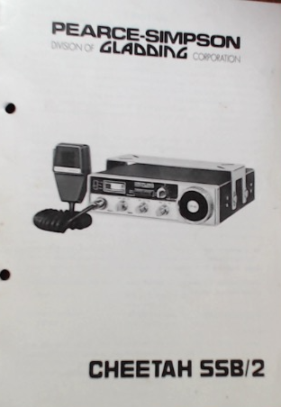
Does this bring back memories?
So, the first step is to see how hard it is to generate the codes needed to drive the D858 PLL chip. This chip has a BCD input, not straight binary as the PLL020 an similar types do.
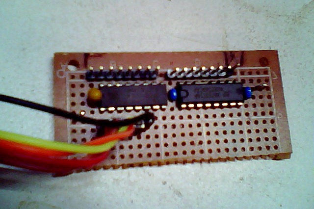
Last night, I tossed some Arduino code together. This is a proof of concept and does not yet drive the CB.
The final HEX number produced needs to be written out to the D858, maybe with a shift register or an I2C port expander. As it is is more that 8 bits, a 16 bit chip will be used and the other bits will be available for more functions.
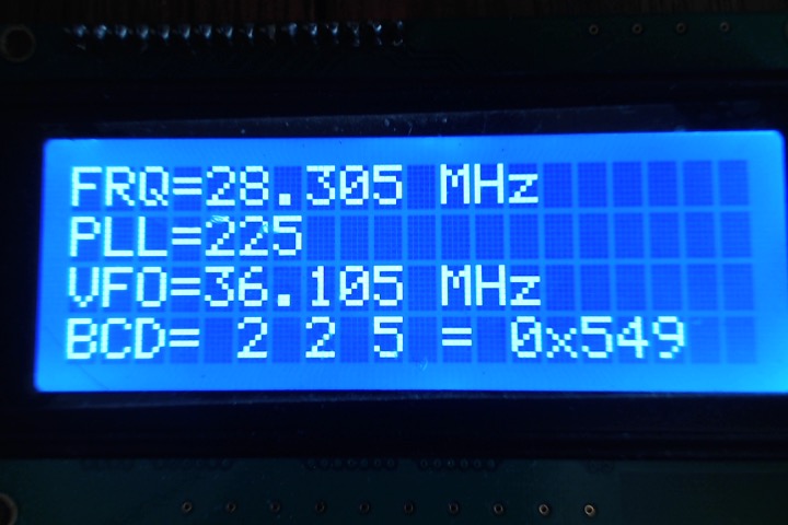
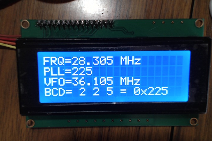
Here is the test display.
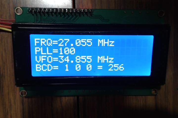
Bottom of the band.
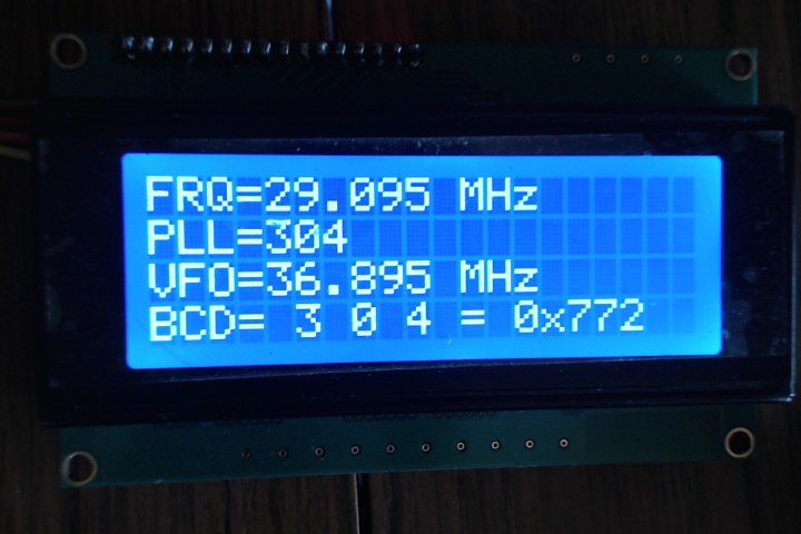
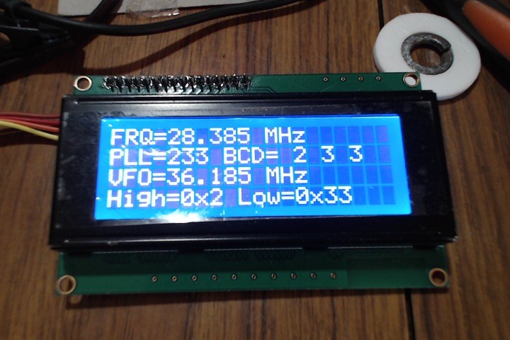
Top of the band.
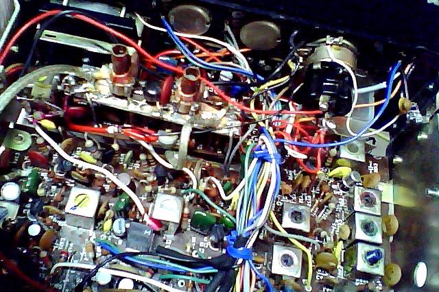
Earlier, testing from the CB part to confirm the numbers.
My aim is to put a rig on 28Mhz, and even 52Mhz.
How many others have old CBs sitting around?
EDIT: I actually have the final number displaying in straight decimal, NOT BCD! Ooops. not quite Fixed!
See the next post.
We had to scratch our heads a bit to remember the frequency generation numbers for the D858 PLL chips used in the sets in question.
In my "treasures" I fund the Pearce-Simpson Cheetah SSB/2 book that had a block diagram in it.
Does this bring back memories?
So, the first step is to see how hard it is to generate the codes needed to drive the D858 PLL chip. This chip has a BCD input, not straight binary as the PLL020 an similar types do.
Last night, I tossed some Arduino code together. This is a proof of concept and does not yet drive the CB.
The final HEX number produced needs to be written out to the D858, maybe with a shift register or an I2C port expander. As it is is more that 8 bits, a 16 bit chip will be used and the other bits will be available for more functions.
Here is the test display.
Bottom of the band.
Top of the band.
Earlier, testing from the CB part to confirm the numbers.
My aim is to put a rig on 28Mhz, and even 52Mhz.
How many others have old CBs sitting around?
EDIT: I actually have the final number displaying in straight decimal, NOT BCD! Ooops. not quite Fixed!
See the next post.
Attachments
-
7.2 KB Views: 446
Last edited by a moderator:
")


