Basic Arduino VFO for crystal replacement (FM828 etc)

VK3ZYZ

Moderator
Staff member
Rod, VK3UG, pointed out my FM828 on 6M was a couple of KHz high. As this was an early mod, I had not done the Si5351 calibration.
So, here is the new file. Calibration makes a difference!
 

Attachments

VK3ZYZ

Moderator
Staff member
The above file in post #61, has floats for the CTCSS tone table and uses 26118 bytes or 85% of program storage space, 1072 bytes or 52% for variables.
floatCTCSS.png


The one below uses less as the CTCSS tone table is int, with the frequencies multiplies by 10 to include a decimal point, then converted to float and divided by 10 to restore the DP when used.
This saves a few bytes. Now 26046 bytes or 84% of program storage space, 990 bytes or 48% for variables.
Actually 4 less than displayed as the "OLED" was removed from the version name to make the display better.
intCTCSS.png


No doubt even more memory could be saved with better optimizations.
 

Attachments

VK3ZYZ

Moderator
Staff member
For the Sept 11 2022 Ham Fest, I hope to have a few kits available for the basic VFO. There will be plenty of the bare boards for those who want source their own parts.
Here is the instructions, so far.
 

Attachments

VK3ZYZ

Moderator
Staff member
Pooh!
I just accidentally fed 12V into the 5V of a board and now have a dead Arduino, Si5351 and OLED display! (The Arduino LEDs were all on bright)
Some things even a coffee cannot fix!
 

VK3ZYZ

Moderator
Staff member
I was intending to add a series diode on the input so an extra electro cap could keep the Arduino running when short power glitches happen.
The diode should have been here...
DiodeOnInput1.jpg


But this is what I actually did...
DiodeOnInput2.jpeg

At the time I thought it felt a tight fit so should have paid attention and checked :(
 
Last edited:
V

VK2RK

Guest
Reading the start of this thread, Note of caution using the Nano onboard 5 Volt regulator.

In my solar controllers designs that I have made in the past, I have used the Nano onboard 5 Volt regulator and found issues with both the quality of some Nanos that are clones and not originals (Most on Ebay's are clones).
The voltage drop across the regulator as you know is the source of the heat so if feeding the board with 12 Volts the voltage drop of 7 Volts times the current draw generates considerable heat, thus if drawing say 300 mA the device is dissipating 2.1 Watts that has no real heat sink, the Nano gets quite hot, especially if the heat is not taken away. As a design practice I have limited the running of external devices that draw small amounts of currents, if requiring more that 100 mA in total I have used external regulators of either switch mode or series type.

Hope this helps.
 

VK3ZYZ

Moderator
Staff member
Here is another 2M version. This has the libs removed now. See next post.

EDIT: 20230306 code now is the one to use. The previous one had an error creep in (I could not find what it was) but this works. Some changes from the broken 20200906 version...
For one thing, this works!
The SubTone (CTCSS) table is now defined as "int" with the frequ entered as freqx10 to allow a decimal point. The SubTone routine converts back to float and divides by 10. It could be done other ways but this works.
Also, converting the table to int makes more room so there are now 72 channels.
 

Attachments

Last edited:

VK3ZYZ

Moderator
Staff member
Somehow, the one of the code examples I posted was crook so there is a new FM828A post to replace it. See #68
 

VK3ZYZ

Moderator
Staff member
I'm working on another software mod that was inspired by the IC22S version that has adjustable CTCSS tones.
Here is a version on progress that has 40 channels and the CTCSS tones are adjustable as are the channel frequencies. So far, the simplex/duplex is still fixed and there is no test to limit out of band when the duplex offset is applied. Also, it would be nice to store the frequencies for later use. I'll need help with that as I have never used that option.
This code uses A3 to select the mode. >200 = set frequ. >400 = set CTCSS. Something else can be added at >550.
Please feel free to have a play.

For some ADC resistors..
Pull down = 10K
buttons with resistors switched to +5V..
22K reads about 320.
10K reads about 512.
6K8 reads about 609.

Both 22K and 10K together = close to 6K6, so that will give you 4 states with 2 buttons, including 0V.
EDIT: Updated code at 17:25 20230315 and some resistors?
1678866992205.png
 

Attachments

Last edited:

VK3ZYZ

Moderator
Staff member
Normal display...
Photo on 15-3-23 at 7.37 pm.jpg
(As shown previously, the frequency inverts on TX.)

Here is the CTCSS shown inverted when editing.
Photo on 15-3-23 at 7.37 pm #3.jpg

And now, the editable part of the frequency display is inverted while the frequency is being edited.
Photo on 15-3-23 at 7.38 pm.jpg

Just the offset stuff to do and of course, the save command.
 

Attachments

VK3ZYZ

Moderator
Staff member
I've tried to make the code for this FM828 almost the same as that for the IC22S, except the synth/PLL driving part.
Also, more comments are in the code to help debugging it.
When there are more fixes, I'll update both.
 

Attachments

VK3ZYZ

Moderator
Staff member
I'm thinking of a version 4!
1726713443960.png

This has some surface mount parts as this is easier to build.
1726713569579.png

It may be better to just do a PCB and add all the parts, not an Arduino and Si5351 board but this is easier.
 
Last edited:

VK3ZYZ

Moderator
Staff member
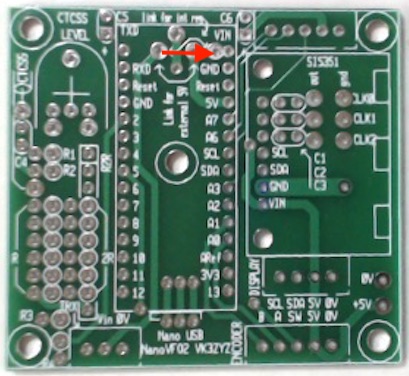
C5 ad C6 are best added after the Arduino Nano is installed as they are pretty close to it. Note the polarity, otherwise smoke will come!
NanoVFO4topParts.jpeg


C5 -C7 are only installed if the Si5351 board SMA connectors are not used, and a DC coupling cap is needed. Then, the signal is fed from the large pads. If no coupling cap is needed, the coax can be soldered to the Si5351 board SMA pads or these pads and C5 - C7 linked out.
NanoVFO4btmParts.jpeg


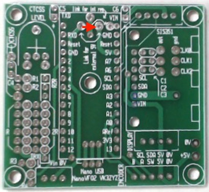
It is best to add the power selection links under the PCB. I should have updated the silk screen that way, sorry.
The green shows the link to use the Nano's internal 5V regulator an that is quite ok for most applications. If mo 5V is needed, for example, a large back light power, a 7805 regulator can be added under the pcb (red). Or, if the set only has 5V available, then the blue link can be installed to make use of that external 5V supply.
NanoVFO4PowerLinks.jpg
Photo on 4-11-24 at 3.29 pm.jpg


Just to add to the confusion, I used a red wire for the "green" option, that is, the Arduino Nano's internal regulator.
Photo on 4-11-24 at 3.29 pm #2.jpg
 
Last edited:

VK3YNV

Administrator
Staff member
Started on the first 828 conversion, The PCB is mounted in a tray which is hotmelt glued to the aluminium frame.
I got some RG316 cables with SMA connectors, and just cut in half and trim to length to feed the receiver and exciter boards. Saves fiddling
around with SMA terminations. The tray STL file is attached. And the front panel STL file is also attached. I just highlighted the raised text
with a white paint marker. I'm thinking I should stop the print when it gets to the start of the text and change filament colour?

There is also a piece which goes on the back of the front panel, I will attach a picture of how it goes together when I figure it out :)


IMG_6184.jpg


IMG_6185.jpg

IMG_6187.jpg
 

Attachments

Last edited:

VK3ZYZ

Moderator
Staff member
I like the FM828 front panel Ray.
On my Wombot, I add this pause code to manually change filament between the layers as needed.
Edit as below, in this case, just before layer 8.

EDIT: This is from the code I used for the print. 0.25mm layers so 2 layers for the text.

G0 X137.381 Y145.107
G0 X137.343 Y138.43
;TIME_ELAPSED:4715.364496

; begin layer pause code
M300 S440 P1000
G91 ; Put in relative mode
G1 Z10 ; Lower bed by 10mm
G90 ; Put back in absolute mode
G1 X0 Y0 ; Zero (home) the X & Y
M84 S0 ; Disable the stepper motor timeout
M0 WHITE then Click To Restart ; Pause and wait for the user. Edit the M0 message to be displayed on the screen as a hint if required.
M84 S60 ; Reenable the default timeout
G91 ; Put in relative mode
G1 Z-10 ; Raise the bed back up 10mm
M300 S440 P100
G90 ; Put back in absolute mode
; end layer pause code


;LAYER:8
;TYPE:WALL-OUTER
;MESH:FM828Front2.stl
G1 F2700 E2728.91507

The result...
FM828Front.jpg
 
Last edited:
Top