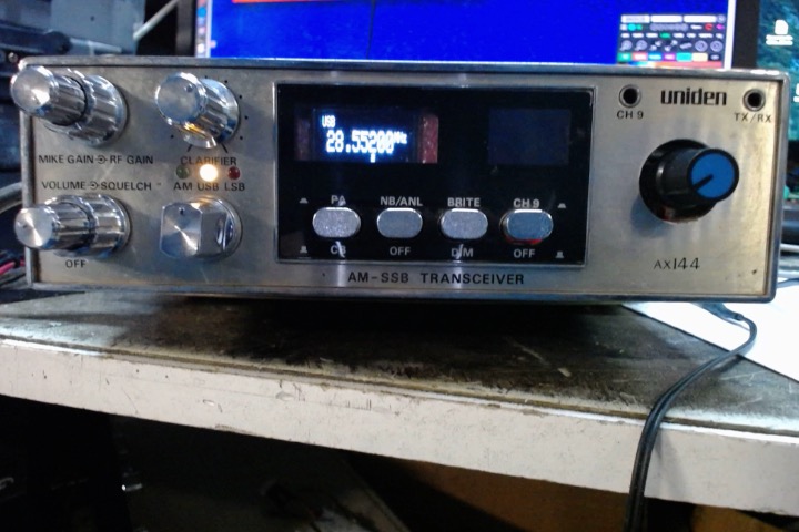
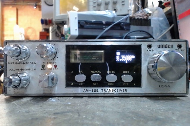
I've started on the AX-144 CB chassis.
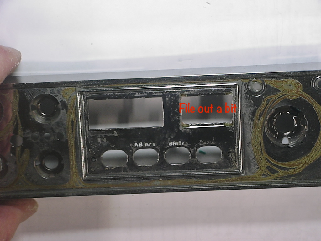
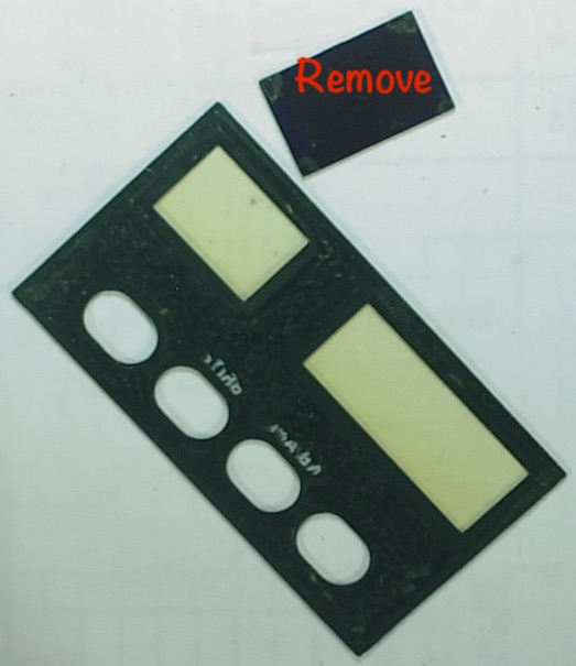
First, I removed the channel switch and display.
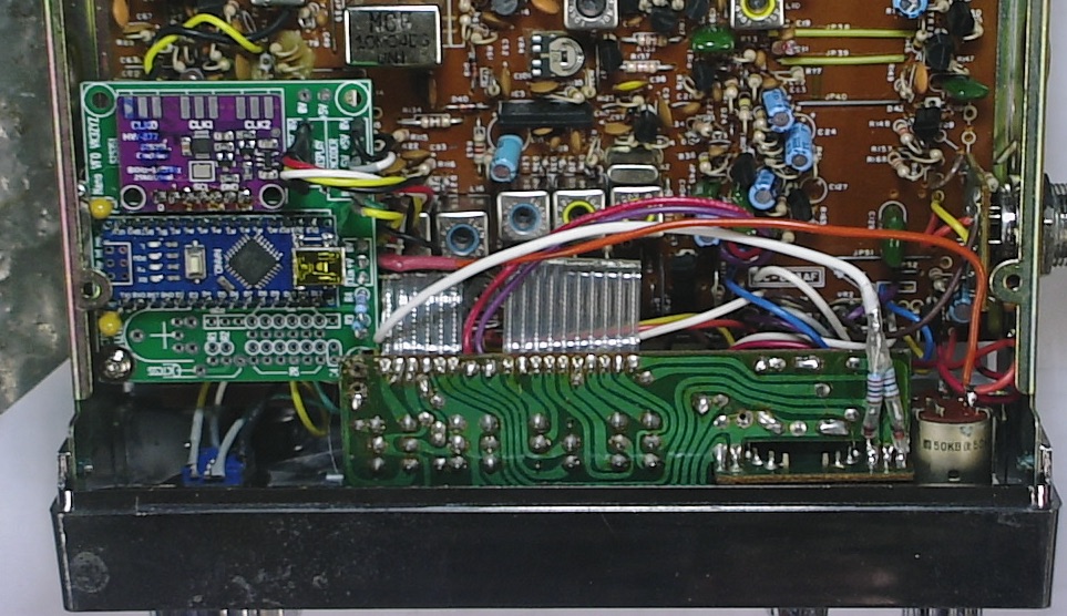
Then, TR19, TR20 and TR22, along with the PLL chip.
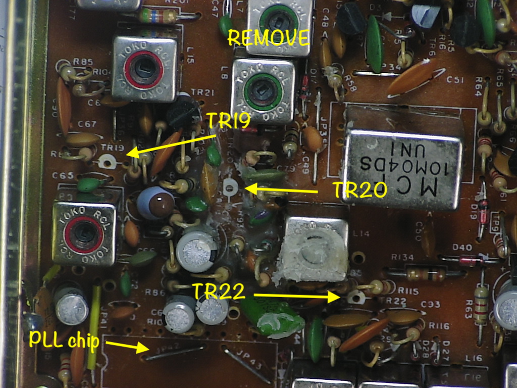
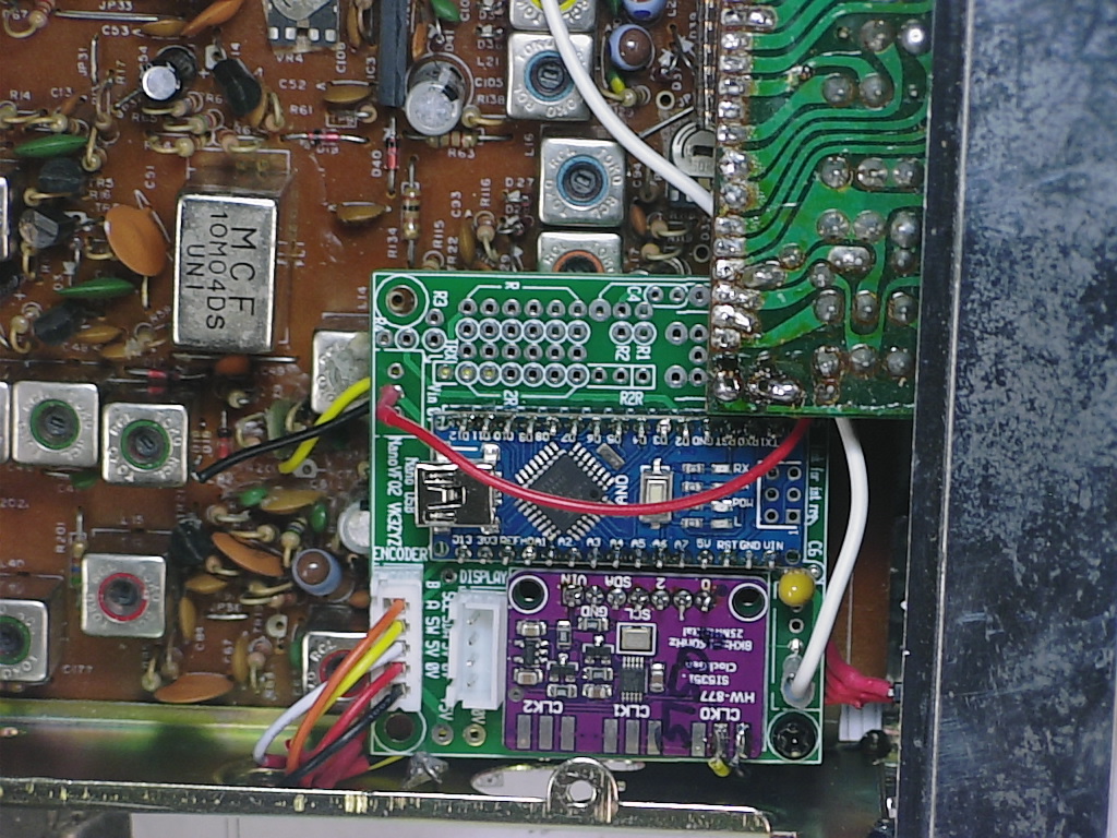
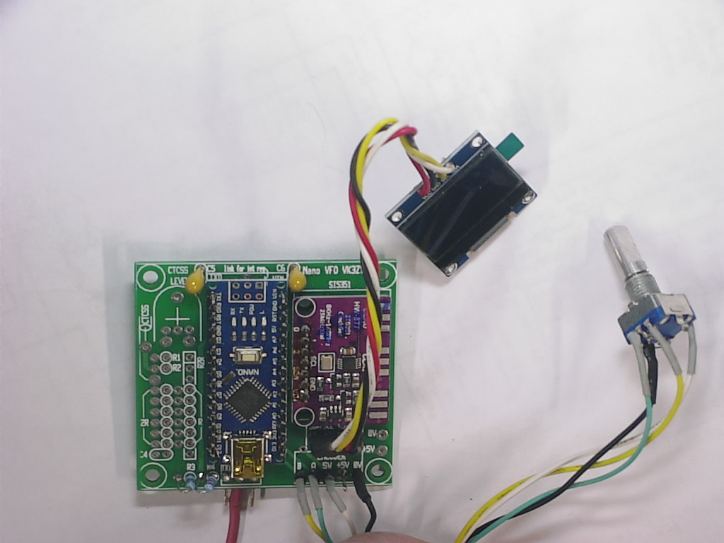
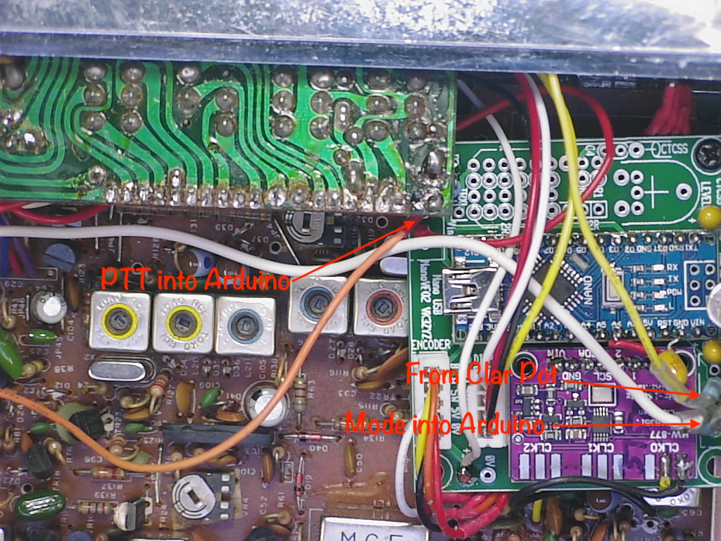
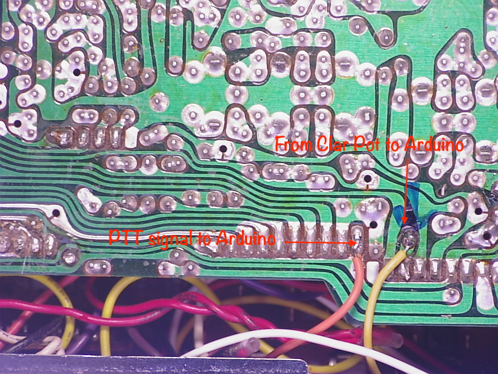
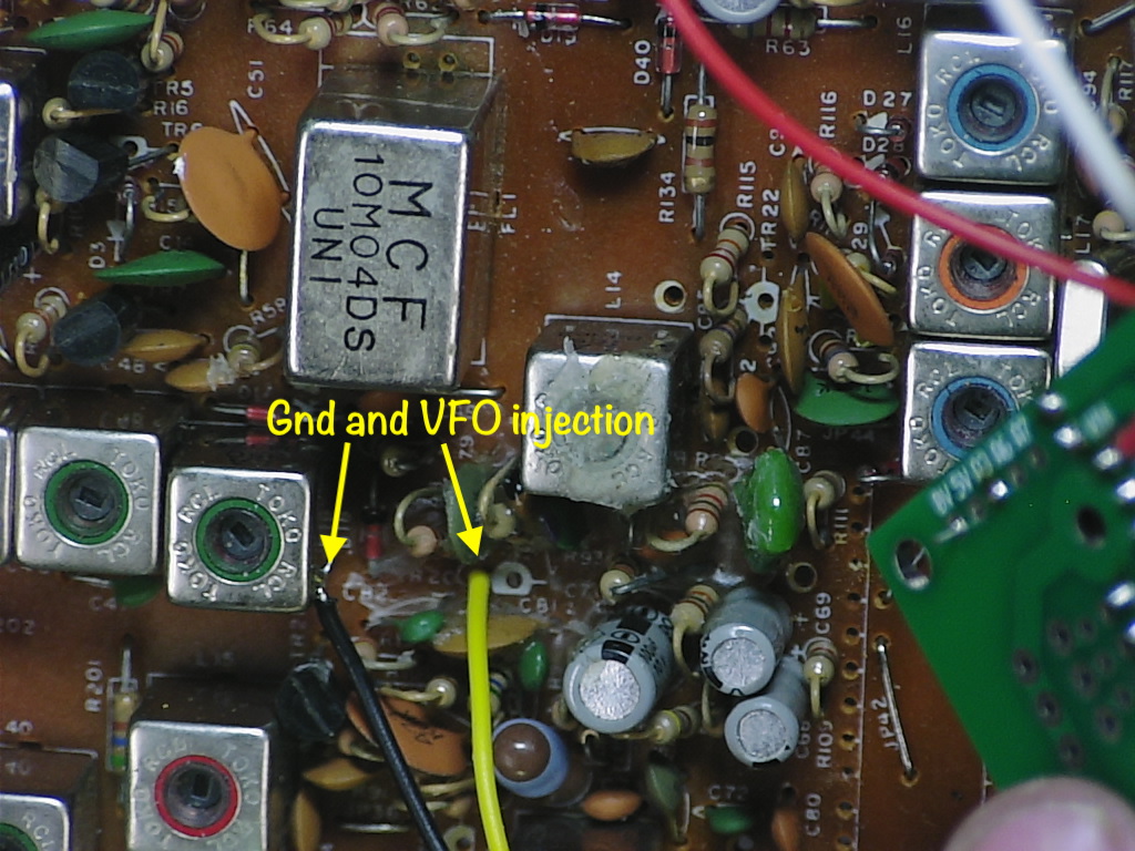
I'm using one of my Arduino synth boards to produce the VFO signal, injected to TR20 Emitter.
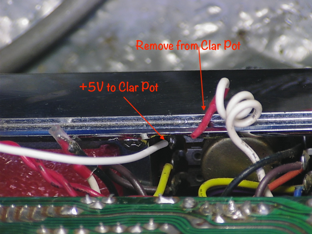
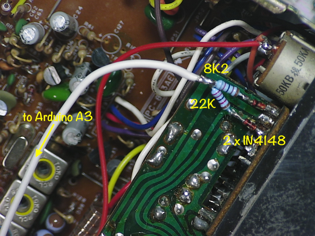
To tell the Arduino the mode, some diodes and resistors are added to the mode switch to produce an analog signal.
I made a mistake in that the leads to the encoder are to short so the board cannot fit with USB access
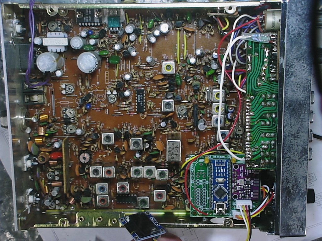
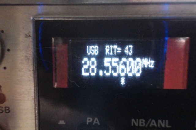
Also, the OLED display is not fitted as the only ones I have are Yellow/Blue and that does not show through the coloured front panel.
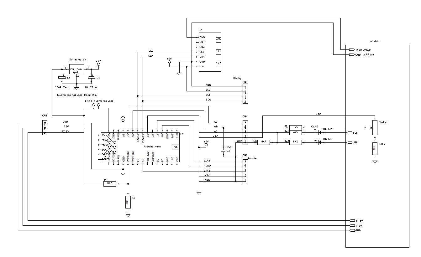
Here is the code so far and I'll add the circuit later.
It also appears I have an intermittent in the AM and the USB does not run. The power feed to the 10.695 crystal is lost somewhere on USB. LSB works on as does AM (most of the time).
To be continued......
EDIT: New code now in post #9
First, I removed the channel switch and display.
Then, TR19, TR20 and TR22, along with the PLL chip.
I'm using one of my Arduino synth boards to produce the VFO signal, injected to TR20 Emitter.
To tell the Arduino the mode, some diodes and resistors are added to the mode switch to produce an analog signal.
I made a mistake in that the leads to the encoder are to short so the board cannot fit with USB access
Also, the OLED display is not fitted as the only ones I have are Yellow/Blue and that does not show through the coloured front panel.
Here is the code so far and I'll add the circuit later.
It also appears I have an intermittent in the AM and the USB does not run. The power feed to the 10.695 crystal is lost somewhere on USB. LSB works on as does AM (most of the time).
To be continued......
EDIT: New code now in post #9
Last edited: