Another use for a PIC12F629?

VK3ZYZ

Moderator
Staff member
I have over 400 of these 8 pin PIC s.
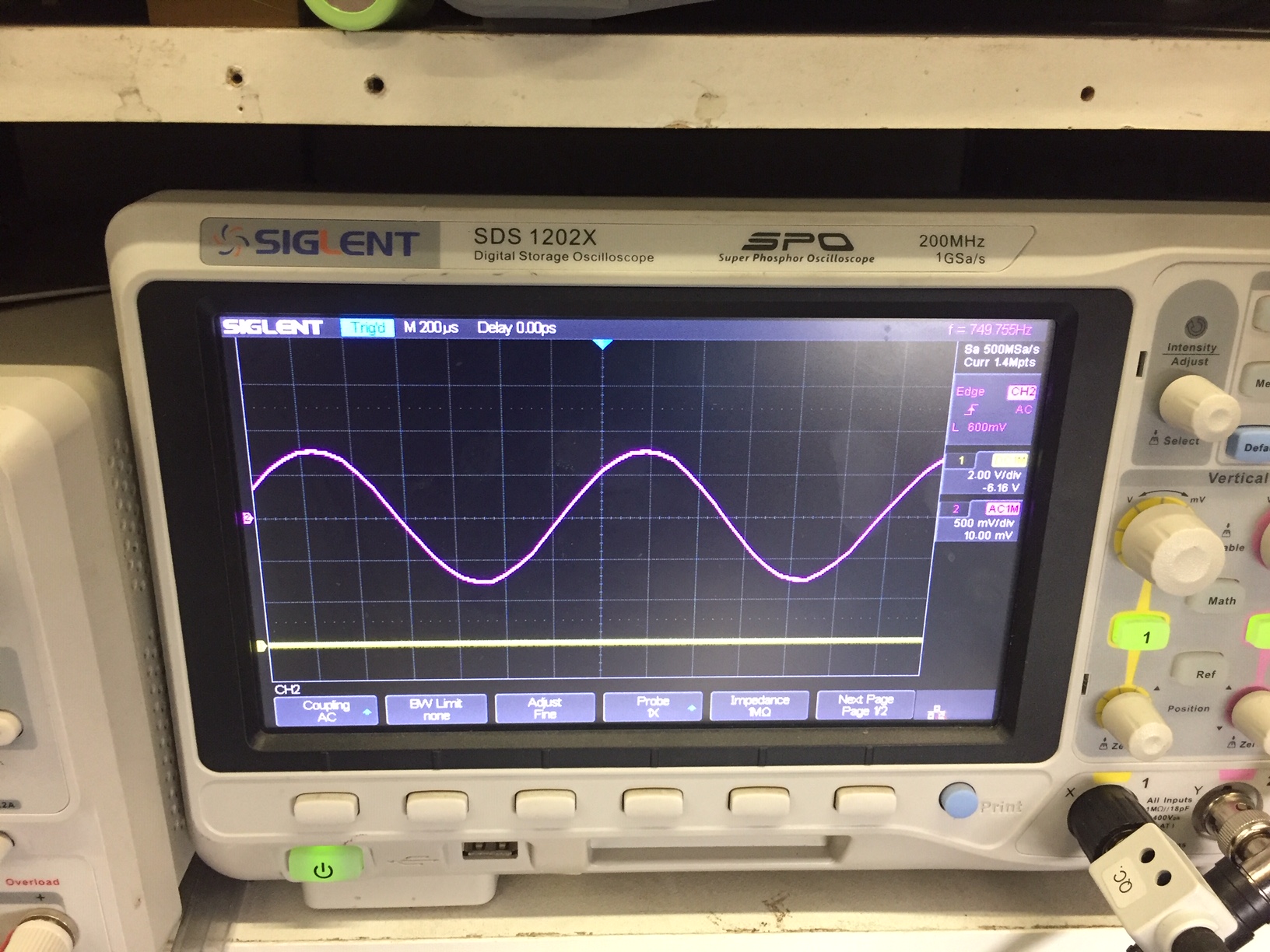
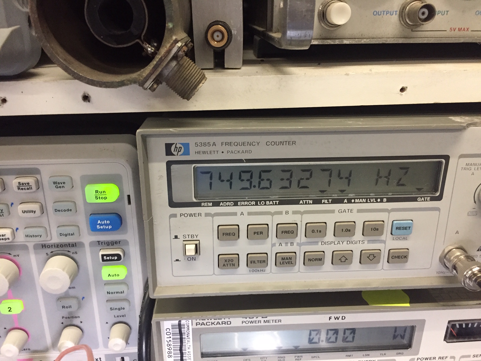
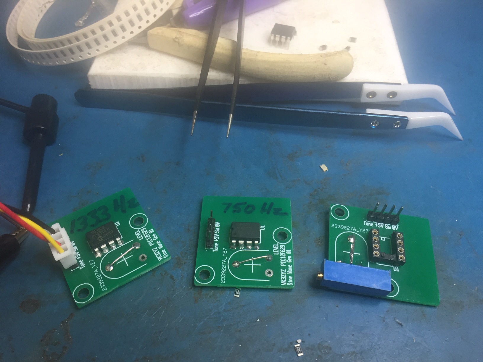
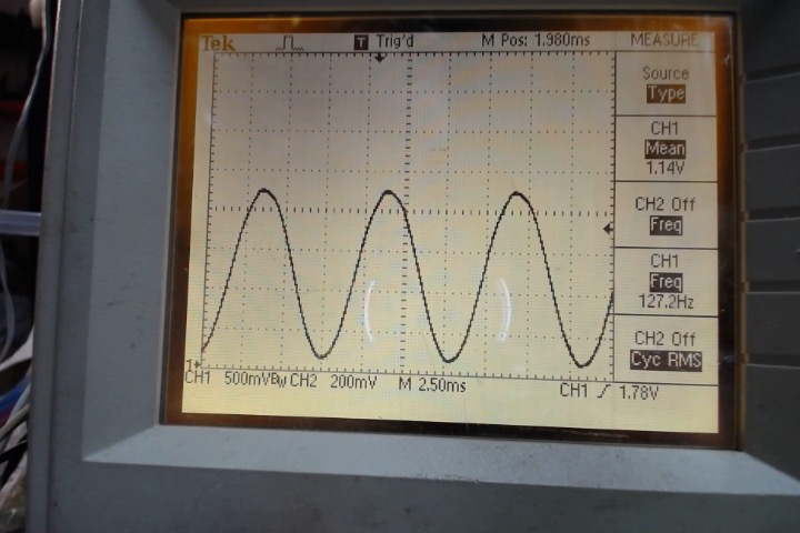
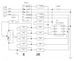
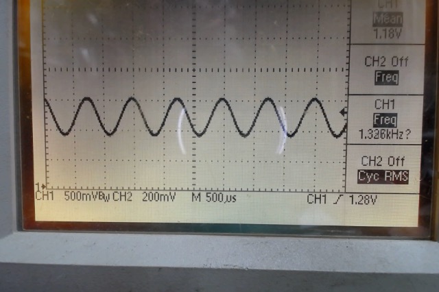
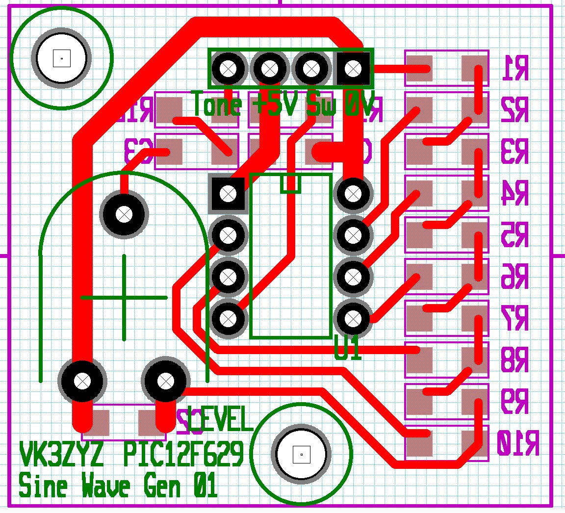
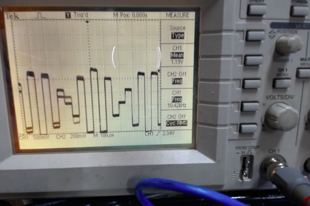
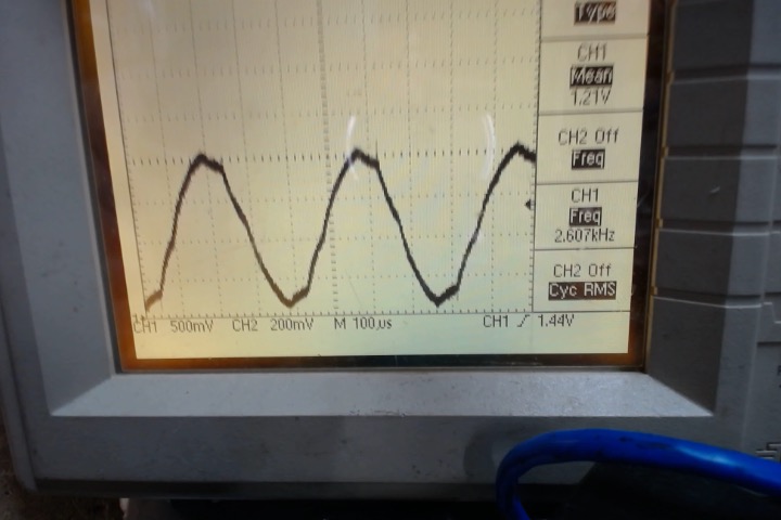
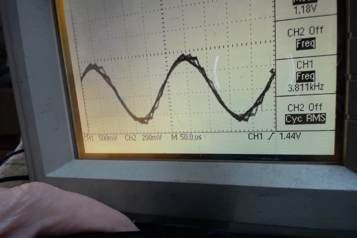
Here is one idea for using them for a sine wave generator.
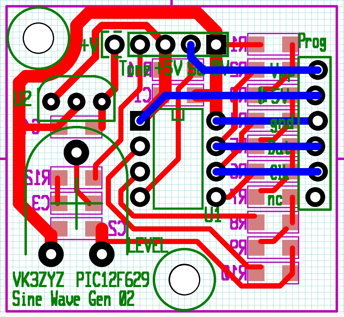
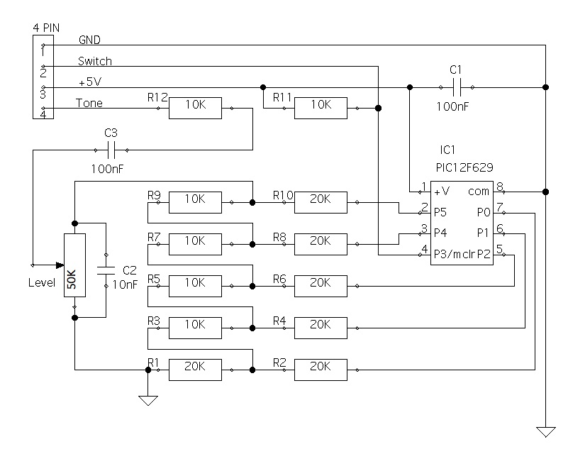
EDIT 20230411 Updated the circuit to suit the PCB.
1681175768175.png

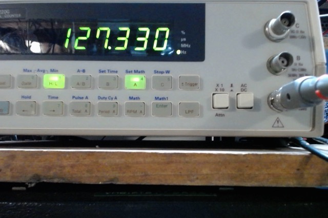
This code, in assembler, produces about 127.3hz for CTCSS use.

Photo on 27-03-2023 at 2.40 PM.jpg


Photo on 27-03-2023 at 2.42 PM.jpg
Photo on 27-03-2023 at 2.43 PM.jpg


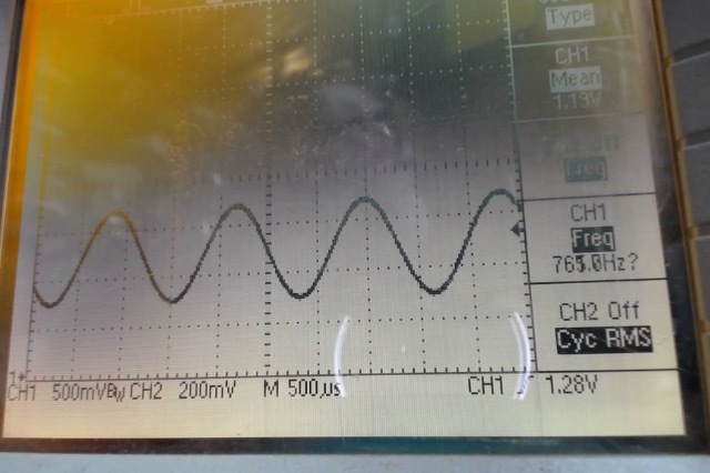
I found the numbers to reload the timer to for a couple of different CTCSS frequs.....

Code:
                                         ; reset Timer1 Low (123Hz)   0F
INT   movlw     0x17        ; reset Timer1 Low (127.3Hz) 17
        movwf     TMR1L
        movlw      0xFF        ; reset Timer1 Hi
        movwf     TMR1H
It would be nice if the timer reload on overflow but...
EDIT: Thanks ray for the code posting pointers.


Any ideas for more uses of these PICs?
 

Attachments

Last edited:

VK3YNV

Administrator
Staff member
How about a 2 tone generator for SSB transmitter testing? The tones need to be in the voice frequency range and non harmonically related.

I've seen 750 Hz and 1333 Hz used, but you could use others.

Maybe use two PIC's and a resistive combiner. Need to be able to adjust the level for each tone independently.


To display formatted code on a forum post, use the CODE /CODE tags

Code:
; reset Timer1 Low (123Hz) 0F
    INT movlw 0x17         ; reset Timer1 Low (127.3Hz) 17
    movwf TMR1L
    movlw 0xFF             ; reset Timer1 Hi
    movwf TMR1H
 
Last edited:

VK3ZYZ

Moderator
Staff member
Code:
INT    movlw     0xDF        ; reset Timer1 Low 763hz
    movwf     TMR1L
    movlw     0xFF        ; reset Timer1 Hi
    movwf     TMR1H
Photo on 27-03-2023 at 6.58 PM.jpg


Code:
INT    movlw     0xF0       ; reset Timer1 Low 1330hz
    movwf     TMR1L
    movlw     0xFF        ; reset Timer1 Hi
    movwf     TMR1H
Photo on 27-03-2023 at 7.02 PM.jpg

I find the 1330hz is drifting about a cycle on my test setup.
It is getting close to the max!
 
Last edited:

VK3ZYZ

Moderator
Staff member
EDIT: Here is an updated board with the surface mount parts on the bottom. Now, this board could be a single sided one.
The gerber files are included and I have ordered 25 boards.
PIC12F629 SineWaveGen01.jpg
 

Attachments

Last edited:

VK3ZYZ

Moderator
Staff member
This mod to the code allows the GPIO3 pin to select the 2 CTCSS frequencies used on the repeaters, or pretty close to them anyway.
123.4hz and 91.4hz
I am trying to work out a spreadsheet to calculate the values and it almost works. I think a nop may need to be added to part of the IRQ loop to equalize both paths.
Here is the MPLAB project and my attempt at a spreadsheet. Please feel free to do better!

Code:
INT    btfss    GPIO,.3        ; read the input switch
    goto    Freq2        ; open, set to 123.6Hz for timer1...
    nop            ; pad to try to get the spreadsheet cals to work
    movlw     0x13        ; set Timer1 Low
    movwf     TMR1L    
    movlw     0xFF        ; set Timer1 Hi
    movwf     TMR1H    
    goto    IRQ_end
    
Freq2    movlw     0xBC        ; closed, set Timer1 91.4hz
    movwf     TMR1L    
    movlw     0xFE        ; set Timer1 Hi
    movwf     TMR1H    
        
IRQ_end    movf    Count,w        ; get the count
    andlw    0x1F        ; mask out unwanted bits. so = 0 to 31
    call     table        ; get the value from the table
    movwf    GPIO        ; write to the port.
    incf    Count,f
    bcf    PIR1,T1IF   ; enable next irq    
    retfie
 

Attachments

Last edited:

VK3YNV

Administrator
Staff member
Another option, I have a pcb is suited to the PIC12F629, it has three FET outputs, originally intended to drive high current strings of RGB Leds.

LS_RGB.jpg


There is provision for a Recom three terminal regulator, and a ttl level serial interface.

I will build a couple up and post some sample code.
 

VK3YNV

Administrator
Staff member
Here is some untested code for generating sine waves using the DDS algorithm. I will test this when Denys's new boards arrive, but it compiles and runs under MPASM, not the XC8 assembler, so use MPLAB 5.35 or earlier.

This version uses a 24bit accumulator, and runs at 25 kHz, each interrupt the accumulator is incremented by a fixed amount, the accumulator rolls over automatically overflowing at 24 bits or 16,777,216, which co-oresponds to one full rotation of the phase angle.

Only the top 5 bits in the accumulator are used to drive the D/A ladder, so they are rotated right and masked. before writing to the D/A

I notice the RC oscillator needs some tweaking to get the frequency right. Not sure if it makes more sense to adjust the interrupt rate or try to play around with OSCCAL. I have some chips that come up with invalid oscal value?

If you want to know more about the algorithm go to https://vanhunteradams.com/DDS/DDS.html
 

Attachments

VK3ZYZ

Moderator
Staff member
I have tried the code. At first there was just a steady 1.1V out until the smoothing cap was removed. Now this is visible...
Photo on 11-04-2023 at 9.37 AM.jpg

I will fiddle with it to try to change the frequency to see what gives...
 
Last edited:

VK3ZYZ

Moderator
Staff member
Well done Ray, your code works!
I have started to play with it and found making the loaded number smaller makes it work.
The frequency set was too high for the poor little PIC12!

Code:
    movlw    0x0a        ; set increment N
    movwf    N
    movlw    0x3d
    movwf    N_1
;    movlw    0x70
    movlw    0xff
    movwf    N_2
Editing N_2 to 0xff produces a 62h=Hz sine wave and to 0xf0, 1.284Khz.
 
Last edited:

VK3ZYZ

Moderator
Staff member
It does look like quite fine tuning on the N value is possible.
0xf00000 = 1.301Khz.
0xf01000 = 1.296Khz
0xf02000 = 1.291Khz.

0xf10000 = 1.220Khz
0xf20000 = 1.139Khz

Code:
    movlw    0x50        ; set increment N
    movwf    N
    movlw    0x7d
    movwf    N_1
    movlw    0xfe
    movwf    N_2
gives 123.0xx Hz. It does wander a bit and may be set a bit better.
On this IC, it is 123.080 +/- .015
 

VK3ZYZ

Moderator
Staff member
0xE00000 = 2.607Khz but it looks a bit crook.
You can see it is not using all the bits.

Photo on 11-04-2023 at 1.25 PM.jpg


Photo on 11-04-2023 at 1.29 PM.jpg

Similarly, 0xD00000 gives 3.905Khz with distortion but it could be quite usable.
I have not yet pushed it to the max.

This is so much better than the way I did it! Thanks Ray.
 
Last edited:

VK3YNV

Administrator
Staff member
Looks promising, I must do a spreadsheet to calculate the N values for different frequencies.
I'm surprised it got up to as fast as 3.9 kHz.
 

VK3ZYZ

Moderator
Staff member
The boards have arrived and they work :)
SineWaveGenTop.jpg
SineWaveGenBtm.jpg
You may note I have used 22K resistors, in fact, if you look closely, in some places, there are two, one on top of the other. This is because I do not have 20K 1206 resistors, so 22K were used in stead, and 2x22K are used for the 11K.
As long as R and 2R is used, the value is not critical.


123Hz.jpg

But I forgot to tick the bottom silk :(
BtmSilkValues.png
Here it is.
 
Last edited:

VK3YNV

Administrator
Staff member
First test with new PCB,
Interrupts running at 20 kHz,

123 Hz calculation
(123/20000)*16,777,216 = 103180 == hex 0x01930C

Modifiy Code with new value for increment

Code:
    movlw    0x0C       ; set increment N
    movwf    N
    movlw    0x93
    movwf    N_1
    movlw    0x01
    movwf    N_2
Measured frequency 106.38 Hz, so maybe interrupt rate is not exactly 20kHz with internal RC oscillator

Correction for measured interrupt frequency
(16,777,216/119,490)=17,270 Hz
(123/17270)*16777216 = 119,490 == hex 0x01D2C2 Measured 122.98 Hz

Trying for 750 Hz
(750/17270)*16,777,216 = 728,599 = hex 0x0B1E17 Measured 750.8 Hz
Correction 750/750.8 = 0.998934, 728,599 * 0.998934 = 727,822 = hex 0x0BB01E Measured 749.6 Hz

Heating with a soldering iron causes the frequency to drift up.
IMG_5101.JPG

IMG_5102.JPG


Updated Code with values for 750 Hz
 

Attachments

VK3YNV

Administrator
Staff member
Checking the interrupt frequency.
Instead of 50us between interrupts, I measure 57.9us ==> 17.268 kHz instead of 20 kHz
so tweaking timer 1 preset values. Instead of 0xFFCE add another 8 clocks ==> 0xFFD6 ==> Measures 19.985 kHz


IMG_5103.JPG
IMG_5104.JPG


Trying for 1333 Hz with corrected interrupt timing.

(1333/20000)*16,777,216 = 1,118,201 = hex = 0x110FF9 measures 1342.8
Correction (1333/1342.8)*1,118,201 = 1,110,040 = hex 0x10F018 measures 1333.0 Hz

So calibration done, here are the assembled boards, I only made one with sockets. The two 750 Hz and 1333 Hz boards are going into an enclosure with level adjust knobs on the front panel, so the on board pot is just linked out.

IMG_5106.JPG
 
Last edited:

VK3YNV

Administrator
Staff member
Here is a spreadsheet with the CTCSS frequencies calculated. The latest code incorporates switching between two frequencies
123 Hz and 91.5 Hz using the GPIO3 input. ( same as Denys's software )

So you can choose two CTCSS frequencies and then switch between the two.

EDIT: Checking the frequency tolerance.
I would expect that typical decoders probably have slightly higher tolerance to frequency errors.

4.7.1 Modulation Code Tolerance and Stability
The CTCSS code frequency shall be within f 0.5 percent (item F) of the assigned value at all times during the standard duty cycle except for the initial two seconds after applying power to the encoder. When the standard encoder supply voltage is varied plus and minus 20 percent, the CTCSS code frequency shall be within f0.5 percent (item G) of its assigned value.
4.7.2 Code Modulation Deviation
The code modulation deviation shall be between f0.5 and k1.0 kHz (item H).
 

Attachments

Last edited:

VK3ZYZ

Moderator
Staff member
1681960937952.png


Updated board for including an on board regulator and programming header.
I found using 1M and 500K (2x1M stacked) resistors for the R2R network, then the PIC will program on board and the sine wave still looks ok.
 
Last edited:
Top