VHF Band pass filter.

BillC

Active member
I have recently constructed a band pass filter which works in the range of 118 to 136 mhz. The insertion loss is at most about 5db. The images show the construction details and the swept response. Some members may be interested in building a filter of this type . Values of L and C may be varied to suit other frequency ranges.
IMG_4217.JPG
IMG_4210.JPG
 

VK3ZYZ

Moderator
Staff member
I see you make use of the "gimmick" capacitors for the coupling there Bill.
The response curve looks good!
 

BillC

Active member
The design value for those two coupling capacitors is about 1.8 pf. These were measured and trimmed before soldering into place.The inductance values are all 100nH ... 5 turns on a 1/4'' whit. bolt, compressed or expanded under test. Interesting to build and test.
 

VK3EB

New member
Bill, the response is looking very good, so much easier with the Rigol to see what's happening.
Dallas
VK3EB
 

BillC

Active member
Yes Dallas, it is a good thing the Rigol. It is just about impossible to adjust a filter like that without the ability to sweep. I am surprised at the reasonably good result of the filter as tested. It needs to see a 50 ohm load especially at the output, So the 50 ohm resistor which is now across the output should probably stay in place so as to define the load. The 5db loss through the filter could nearly be made up by an efficient antenna ? I am considering constructing another filter of the same range but using 4 turn coils wound on a 5/16 w bolt as the former also would make all the caps adjustable (trimmers) it would be a bit more messy to construct ... see how we go.
 

VK3EB

New member
Thanks for building the filter hope its not taking up to much time on other activities around the farm! I agree the termination should stay, loss thru the filter is not a problem an antenna cut for aircraft band is a sort of filter in its own right and is what I should have but the discone is handy for general purpose listening. A receiver that goes from 100kHz to 1000Mhz is never going to work without filtering out the stuff you don't want before hitting the high gain RF front-end, the Icom R6 is great with a short whip but useless on a real antenna outside, up high.

Bill, I must question you construction methods! I've always wound my small coils on the shank of twist drills will they work ok if you wind them on Whitworth bolts?:)
 

BillC

Active member
Hi Dallas. I think the idea of winding the coils on a bolt thread is to partly form the pitch or space between turns, the wire size must small enough to follow the bolt thread so as to achieve the desired result. It seems to work quite well and if needed the coil may compressed or stretched to vary the inductance a bit. I built another filter today with all caps. adjustable ...no good, best I could get was plenty of ripple around 10 db loss. I have found in the past that the best way to couple between the filter stages is to use the twisted wire capacitor, (gimmick) and the same idea holds true today. Thanks for giving me the chance to speriment with the filter. Catch up soon.
 

VK2RK

Active member
Hi Bill

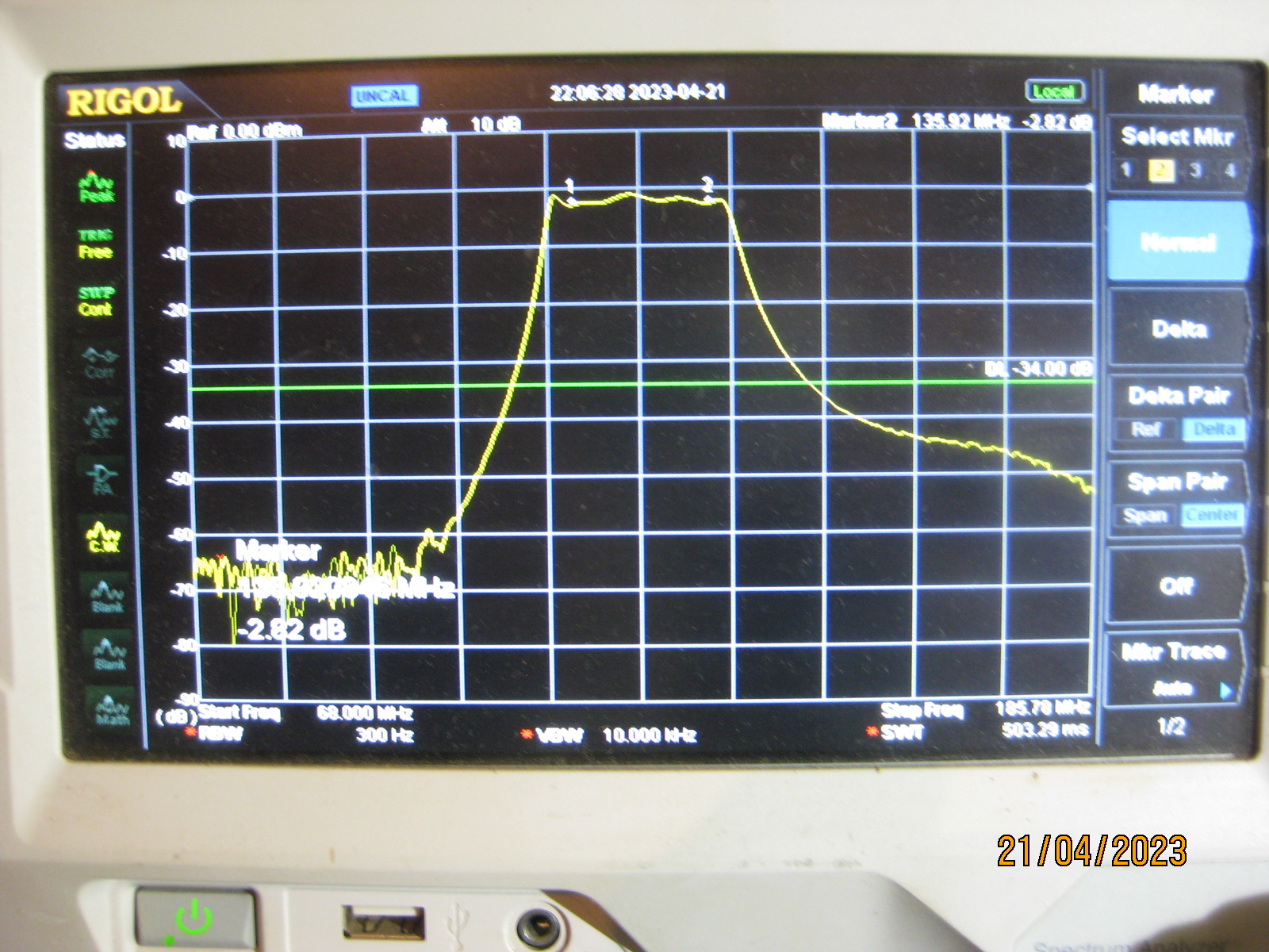
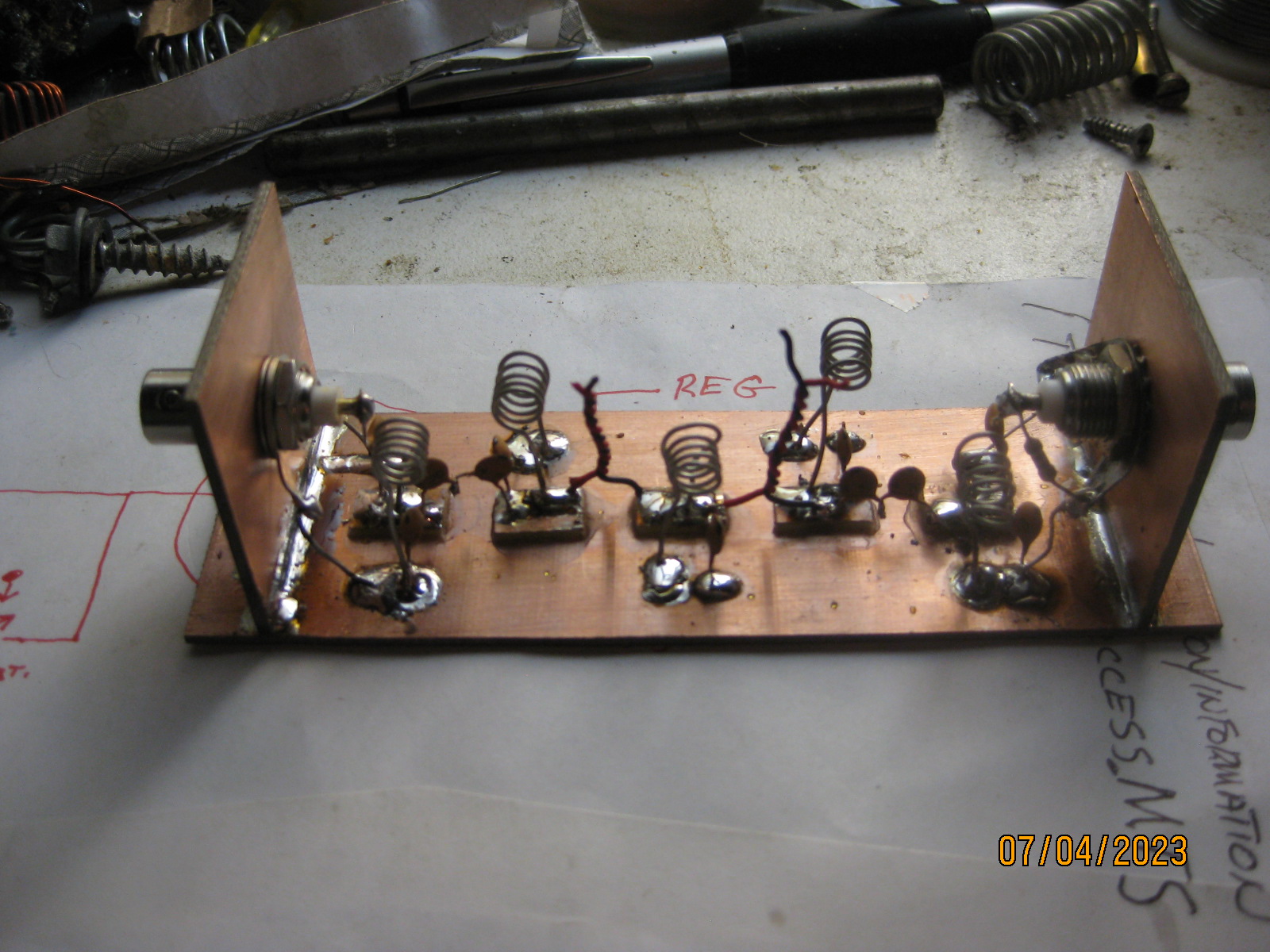
I tend to agree with Dallas, however the result you achieved is outstanding, the only issues I have is the temperature and mechanical stability, I note that you are addressing this by constructing using adjustable capacitors, that you did not achieve the desired result.

You have to allow for stray coupling something that you cant visualise and will very with layout.
In the industry when required to design built a high Q filter or preselector that provided both mechanical and temperature stability on the higher frequencies (VHF UHF the window coupling technique is used ) utilizing Parallel LC, usually 4 to 6 cells achieving the passband required, the 50 Ohm match using a C divider. This method of design allows variable passband utilizing stagger tuning, the return loss off memory is less than 3 dB
The stability is achieved by mechanical construction.
Both Motorola and Philips used this technique, with Philips on PCB construction the coil shield (Can) would have a slot that aligned with the next coil.
Not so good in my mind, Motorola would use a extruded alloy block, RCA and GE radios used the same as Motorola.

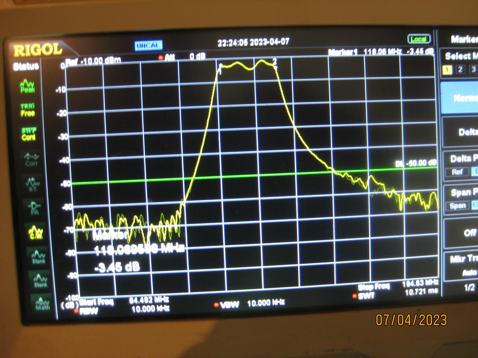
BTW meant to say that ripple is not necessarily due to filter ringing, but bad matching from generator to load in that the return loss current interferes with the main frequency time domain waveform.
 

BillC

Active member
Hi Rob. Thanks for the comments on the filter etc. I have built slot coupled filters in the past, I did not consider that system for this particular job as I doubt that it would provide the desired result for such a wide frequency range ..118 to 136 mhz a band width of 18 mhz. You may note that the image of the swept response relates to the first filter which I constructed, the image of the filter unit is also shown. Close inspection of the image of the filter will show that the coils are placed in such a way that they do not magnetically couple, this has been tested by moving temporarily grounded brass shields around the filter body in various places while watching the sweeping trace. The filter is built using a mixture of ceramic capacitors and the homemade twisted wire capacitors, and as previously mentioned the value for those two capacitors is 1.8 pf this is readily obtained with the twisted wire system The small capacitance of the coil mounting pads is factored in with the shunt resonating capacitance of each of the coils. How about we start a build a filter project?
 

BillC

Active member
I have built the third filter in the series , it is constructed using the same build style as the previous two. Initially the performance during alignment was not good , it was impossible to produce a flat top and there was a lot of ripple with the high frequency end falling away in response . So what to do? Place a 250 ohm pot. across the filters output and adjust the pot to give a nice picture on the analyzer . This filter now works very well into a 200 ohm load , with the insertion loss under - 2.8 db over the range 118 to 136 mhz . I reckon most receivers would work well with this filter at the input.
IMG_4221.JPG
 

VK3EB

New member
Hi Bill, looking good your the man! its such a great job you should be designing filters for cigarettes.

Got the antennas on the new mast at Swallow St. with a couple of pulleys for stringing up wire aerials.
Discone_2m70cm_FM vert.JPG
 

Attachments

BillC

Active member
Hi Dallas. The antennas loook realy good, a fair bit of work to put it all together I bet. Hope to catch you soon for a filter drop.
 
Top