VFO Design with Adaptive Step Rate and Vernier Display
- Thread starter sadarc
- Start date
V
VK3ZYZ
Guest
I am playing with getting to understand how the software works. It is a bit of a battle, but some progress has been made.
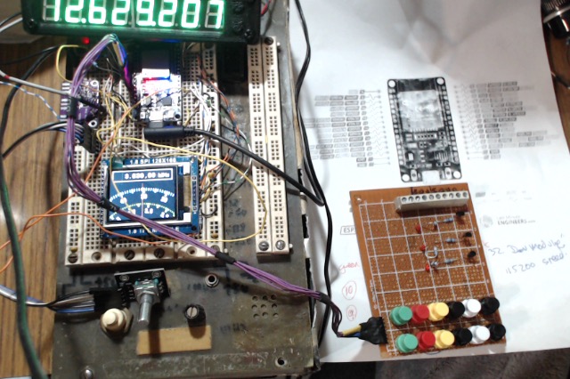
The main mod to the code so far is to have the push button matrix added and now I have a band up and down selection that looks to be working.
See the attached short movie for a demo.
It is a bit untidy, (and singed in a couple of spots), but this breadboard has given me good service for probably 40 years. The case holds a number of functions that may be worth a post of their own.
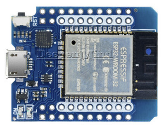
This proto is using s "full sized" ESP32, but I intend to use a physically smaller version.
A MINI D1 ESP-32S as below...

This will fit easier into an existing radio's front panel area.
Here is a bigger one.. But a trap is there are a number off different pin outs with these boards.

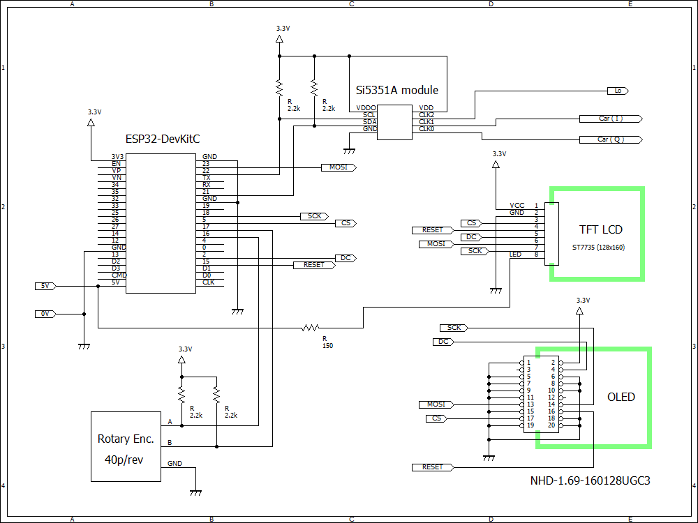
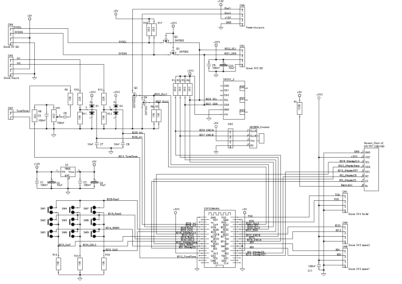
The board design will have 3 oscillator outputs available, and for my application, one will be variable as the main tuning, the second fixed as the second mixer and the third the USB/LSB injection osc.
This is of course up to the user's own need.
There will be a couple of inputs and outputs, and maybe 3 analog inputs so a second small OLED display can be used as an "analog" meter for S, power and VSWR readings.
Here is an example VU meter..

An Arduino library of different meter displays is freely available if you want to play with this. Search "OLEDMeter.ino" or post here and I can put the file up if required. This library is another thing I hope to move to the ESP32, but it may be better to just do a separate Arduino Nano OLED meter board.
The Codan radios also have FWD and REV power sensing built in hence the want for a VSWR meter.
For most radios, we need to sense the PTT signal at the very least.
The Codan does the main control via an I2C (or Cbus for earlier ones) interface. So an external I2C buss level shifted to 5V will be on board. (This ESP32 runs at 3.3V)
Another output this board will generate is a tone for the tune function.
I will update here as progress goes forward.
Please let me know if you have any questions or ideas.
The main mod to the code so far is to have the push button matrix added and now I have a band up and down selection that looks to be working.
See the attached short movie for a demo.
It is a bit untidy, (and singed in a couple of spots), but this breadboard has given me good service for probably 40 years. The case holds a number of functions that may be worth a post of their own.
This proto is using s "full sized" ESP32, but I intend to use a physically smaller version.
A MINI D1 ESP-32S as below...
This will fit easier into an existing radio's front panel area.
Here is a bigger one.. But a trap is there are a number off different pin outs with these boards.
The board design will have 3 oscillator outputs available, and for my application, one will be variable as the main tuning, the second fixed as the second mixer and the third the USB/LSB injection osc.
This is of course up to the user's own need.
There will be a couple of inputs and outputs, and maybe 3 analog inputs so a second small OLED display can be used as an "analog" meter for S, power and VSWR readings.
Here is an example VU meter..
An Arduino library of different meter displays is freely available if you want to play with this. Search "OLEDMeter.ino" or post here and I can put the file up if required. This library is another thing I hope to move to the ESP32, but it may be better to just do a separate Arduino Nano OLED meter board.
The Codan radios also have FWD and REV power sensing built in hence the want for a VSWR meter.
For most radios, we need to sense the PTT signal at the very least.
The Codan does the main control via an I2C (or Cbus for earlier ones) interface. So an external I2C buss level shifted to 5V will be on board. (This ESP32 runs at 3.3V)
Another output this board will generate is a tone for the tune function.
I will update here as progress goes forward.
Please let me know if you have any questions or ideas.
Attachments
-
1.5 MB Views: 591
Last edited by a moderator:
V
VK3YNV
Guest
Looks good Denys, did you get the acceration working? I ordered some Si5351's on ebay, and a few days later the listing was removed, and the seller de-listed? so it looks like I might have to wait a bit longer.
V
VK3ZYZ
Guest
Hi Ray. No, the acceleration does not work as far as I can see, but I now have 2 displays goingLooks good Denys, did you get the acceration working? I ordered some Si5351's on ebay, and a few days later the listing was removed, and the seller de-listed? so it looks like I might have to wait a bit longer.
")

So, I should be able to get the other I2C chips in the Codan going too.
V
VK3ZYZ
Guest
To help limit the problems of wires working loose on the breadboard, I'm going to solder the parts to a proto board and mount them all in a case I just drew up and printed.

This print is a little rough but will work ok.
OOPS!
After printing it out, I realized it was mirrored L-R so I will do another one to keep the display centralized. The cutout is not symmetrical.
This print is a little rough but will work ok.
OOPS!
After printing it out, I realized it was mirrored L-R so I will do another one to keep the display centralized. The cutout is not symmetrical.
Last edited by a moderator:
V
VK3ZYZ
Guest
This is the one I'm working on now.

It has cutouts for the USB plugto the ESP32 board and also a space for the Si5351 coax connectors.
Some holes printed into the front fit push buttons resurrected from an old video player. These are mounted with hot melt into the case, along with the display. Good stuff, hot melt!

This will end up as my development system.
It has cutouts for the USB plugto the ESP32 board and also a space for the Si5351 coax connectors.
Some holes printed into the front fit push buttons resurrected from an old video player. These are mounted with hot melt into the case, along with the display. Good stuff, hot melt!
This will end up as my development system.
V
VK3ZYZ
Guest
It is progressing!

This was taken from a bit of a low angle so one scale is covered by the knob. It is actually visible when looking straight on.

It can be seen here, as are the Si5351 board outputs.

The proto board construction looks a bit rough, but it works ok.

This is what the insides looks like. It has been made so the front can be unplugged from the board.

A closer look at the inside of the front.
I could not get this construction to tune for a bit. Then I realized the pullup resistors on the keypad were missing. Without them, the loop was waiting for the push buttons to be released. I added them but it still would not work
After going back to the original to ensure the encoder was working and the tuning was ok, I had to have a coffee break.
After coffee, I remembered the code was looking for a 3x4 keypad and I'd decided a 3x3 keypad was enough. I'd only added 3 pullups, and the code needed 4!
So, after fixing the code for a 3x3 matrix, it worked again.
There is still lots to do, but this may make it a bit more reliable during development.
This was taken from a bit of a low angle so one scale is covered by the knob. It is actually visible when looking straight on.
It can be seen here, as are the Si5351 board outputs.
The proto board construction looks a bit rough, but it works ok.
This is what the insides looks like. It has been made so the front can be unplugged from the board.
A closer look at the inside of the front.
I could not get this construction to tune for a bit. Then I realized the pullup resistors on the keypad were missing. Without them, the loop was waiting for the push buttons to be released. I added them but it still would not work
After going back to the original to ensure the encoder was working and the tuning was ok, I had to have a coffee break.
After coffee, I remembered the code was looking for a 3x4 keypad and I'd decided a 3x3 keypad was enough. I'd only added 3 pullups, and the code needed 4!
So, after fixing the code for a 3x3 matrix, it worked again.
There is still lots to do, but this may make it a bit more reliable during development.
V
VK3YNV
Guest
Looks good Denys, I'm going to do a Si5351 upgrade for the Philips FM828. So put me down for one of your boards when they arrive.
V
VK3ZYZ
Guest
I tried the HN3806-AB-600N encoder. As it is open collector, 4K7 pullups to 3V3 were added, and the encoder power was from an external plug pack.
Even though it is s'posed to run from 5 to 24V, I found 5V would not work.
The VFO is a lot smoother, but the step and acceleration etc will need to be fiddled to suit as it easily goes too fast.
This quick changes made it better. But that will be worth playing with more later.
#define freq_step 1 // Min step[Hz] <<<<<<<<<< Was 10
/*----------------------------------------------------------
Adaptive step control parameters
-----------------------------------------------------------*/
uint32_t vth=100; // Velocity threshold for acceleration <<<<<<<<<<<<< was 1.
float Racc=0.002; // Rate of acceleration .002
float Rdec=1.0; // Rate of deceleration
float MaxL=1500.0; // Max Step[Hz] = freq_step + Racc*MaxL*MaxL

On Ebay, search for "6mm 600P/R Incremental Rotary Encoder" (or even 300, 100 or 50 in place of the 600), and they are available for around $20.
I think a 100 or even the 50 steps would be better, but I only have the 600 step versions.
I do need to upgrade this USB camera as it will not focus too well, sorry.
An attached video of the proto setup, with the new encoder, in operation is below.
Even though it is s'posed to run from 5 to 24V, I found 5V would not work.
The VFO is a lot smoother, but the step and acceleration etc will need to be fiddled to suit as it easily goes too fast.
This quick changes made it better. But that will be worth playing with more later.
#define freq_step 1 // Min step[Hz] <<<<<<<<<< Was 10
/*----------------------------------------------------------
Adaptive step control parameters
-----------------------------------------------------------*/
uint32_t vth=100; // Velocity threshold for acceleration <<<<<<<<<<<<< was 1.
float Racc=0.002; // Rate of acceleration .002
float Rdec=1.0; // Rate of deceleration
float MaxL=1500.0; // Max Step[Hz] = freq_step + Racc*MaxL*MaxL
On Ebay, search for "6mm 600P/R Incremental Rotary Encoder" (or even 300, 100 or 50 in place of the 600), and they are available for around $20.
I think a 100 or even the 50 steps would be better, but I only have the 600 step versions.
I do need to upgrade this USB camera as it will not focus too well, sorry.
An attached video of the proto setup, with the new encoder, in operation is below.
Attachments
-
2.1 MB Views: 382
Last edited by a moderator:
V
VK3YNV
Guest
Looks to be working well, if you want a custom machined knob let me know.
V
vk3tjs
Guest
Denys, I'll have few boards if that is possible.
V
VK3ZYZ
Guest
A rough parts list for the VFO...
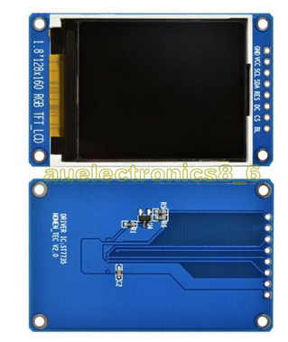
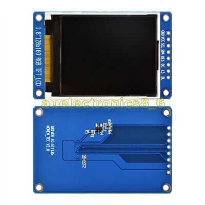 This is the LCD I am hoping to use.
It has less wasted space under the LCD, so a larger diameter encoder can be used and still keep the alignment correct.
 I want to use this form factor as it takes up less board space.
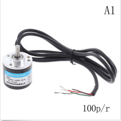
 This is the 100 pulses per rev version. The 600 P/R one I have is too fast. 50P/R encoders are available too, but the price goes up.
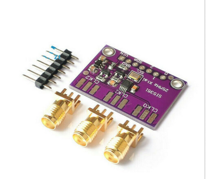
 The magic is with this little beauty. It is able to generate 3 different frequency outputs.
There will be other bits and pieces, like SMA leads, voltage regulators, Rs and Cs,,,,
but this is the main list.
ST7735S 1.8 inch 128X160 SPI TFT LCD full color display module for Arduino AU | eBay
1 x 1.8" ST7735S SPI TFT LCD Display Module. SPI interface. Pixel size. LCD Active area. Input Data. Display Format. Viewing Direction. Display Mode.
www.ebay.com.au
It has less wasted space under the LCD, so a larger diameter encoder can be used and still keep the alignment correct.
MINI D1 Wemos ESP-32S ESP32 WIFI + Bluetooth ESP8266 CP2104 Module | eBay
Find many great new & used options and get the best deals for MINI D1 Wemos ESP-32S ESP32 WIFI + Bluetooth ESP8266 CP2104 Module at the best online prices at eBay!
www.ebay.com.au
100/200/360/400/500/600P/R Photoelectric Incremental Rotary Encoder 5 TFZTHFUK | eBay
Find many great new & used options and get the best deals for 100/200/360/400/500/600P/R Photoelectric Incremental Rotary Encoder 5 TFZTHFUK at the best online prices at eBay!
www.ebay.com.au
Si5351A I2C 25MHZ Clock Generator Breakout Board 8KHz to 160MHz for Ardui*e gv | eBay
Find many great new & used options and get the best deals for Si5351A I2C 25MHZ Clock Generator Breakout Board 8KHz to 160MHz for Ardui*e gv at the best online prices at eBay!
www.ebay.com.au
There will be other bits and pieces, like SMA leads, voltage regulators, Rs and Cs,,,,
but this is the main list.
B
BillC
Guest
Very interesting Denys .good luck. Thanks Ray i tink i on bord crock.
V
VK3ZYZ
Guest
Well, one step closer.
The ESP32 boards arrived today
.
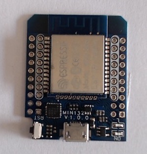
The ESP32 boards arrived today
.
V
VK3ZYZ
Guest
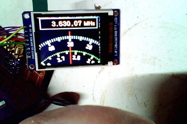
The display I want to use goes ok. There is a bit of a funny around the edges 'tho. It is almost like the display is actually a bit bigger than 128x160.
V
VK3YNV
Guest
Just playing around seeing what it looks like.
The KMR-1.8 SPI displays I bought off ebay have the pins mislabelled. They swapped the SDA and SPI labels.
I am using an ESP32-WROOM module which is 3.3V I/O pins, and you can run the ST7735 direct on 3.3V if you short out a
link on the back of the display PCB which just bypasses the regulator.
Here are the connections that work.
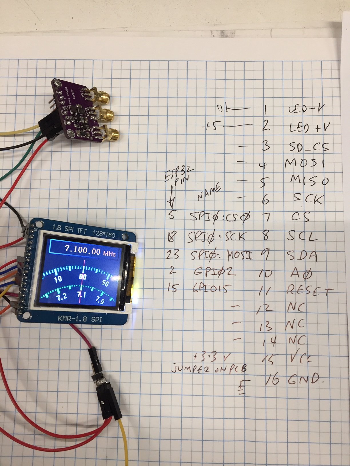
The optical encoder I ordered hasn't turned up yet. So I can't demonstrate the adaptive rate tuning.
The KMR-1.8 SPI displays I bought off ebay have the pins mislabelled. They swapped the SDA and SPI labels.
I am using an ESP32-WROOM module which is 3.3V I/O pins, and you can run the ST7735 direct on 3.3V if you short out a
link on the back of the display PCB which just bypasses the regulator.
Here are the connections that work.
The optical encoder I ordered hasn't turned up yet. So I can't demonstrate the adaptive rate tuning.
V
VK3ZYZ
Guest
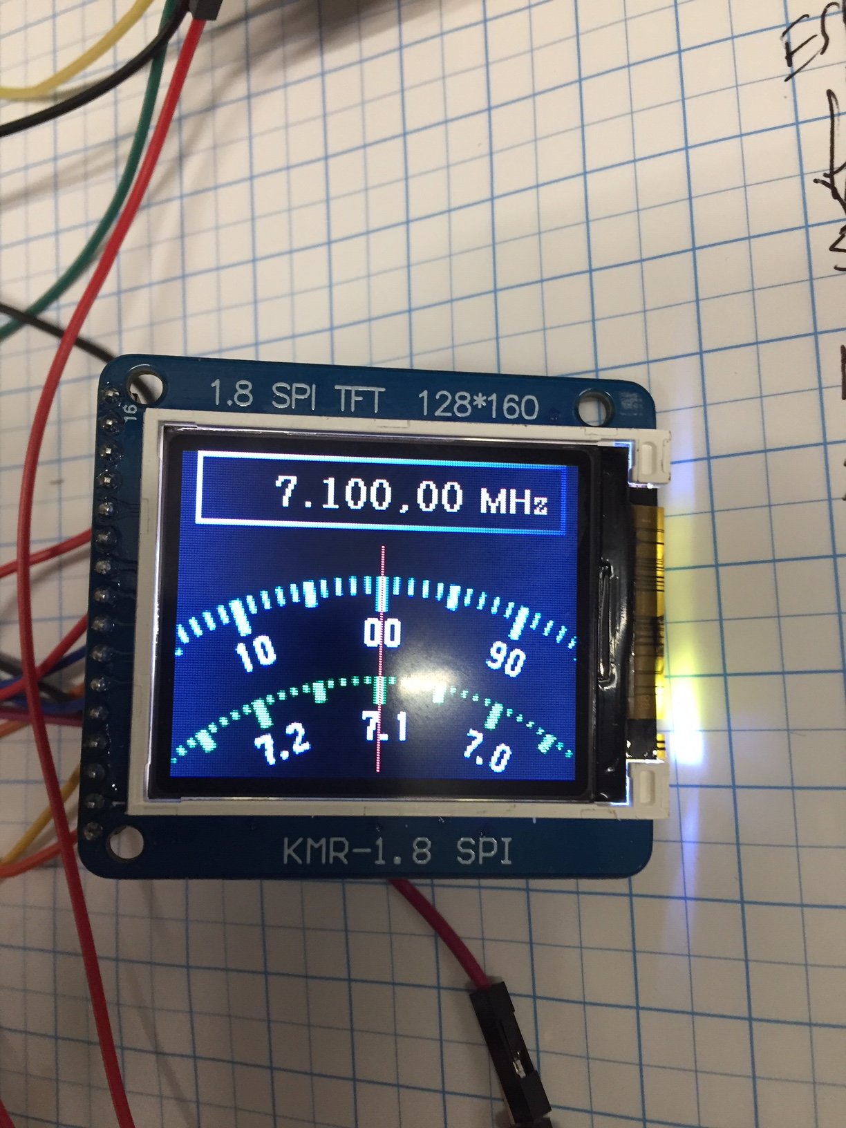
They look good.
I've got to get back to drawing the PCB, stop playing with other things!
I've got to get back to drawing the PCB, stop playing with other things!
V
VK3YNV
Guest
Hi Denys,
I've been researching ST7735 TFT displays, and they are an incredibly mixed bag, almost none are consistent, some reverse red and blue, some have stray pixels on edges some have mislabelled pins ( like the KMR1.8 SPI above ), the most common way of identifying the different types is by the colour of the plastic tab on the protective film.
Here are some of the different types supported by the TFT_eSPI library, mine was a Bluetab, sadly not listed, but REDTAB worked
// For ST7735 ONLY, define the type of display, originally this was based on the
// colour of the tab on the screen protector film but this is not always true, so try
// out the different options below if the screen does not display graphics correctly,
// e.g. colours wrong, mirror images, or stray pixels at the edges.
// Comment out ALL BUT ONE of these options for a ST7735 display driver, save this
// this User_Setup file, then rebuild and upload the sketch to the board again:
// #define ST7735_INITB
// #define ST7735_GREENTAB
// #define ST7735_GREENTAB2
// #define ST7735_GREENTAB3
// #define ST7735_GREENTAB128 // For 128 x 128 display
// #define ST7735_GREENTAB160x80 // For 160 x 80 display (BGR, inverted, 26 offset)
#define ST7735_REDTAB
// #define ST7735_BLACKTAB
// #define ST7735_REDTAB160x80 // For 160 x 80 display with 24 pixel offset
// If colours are inverted (white shows as black) then uncomment one of the next
// 2 lines try both options, one of the options should correct the inversion.
// #define TFT_INVERSION_ON
// #define TFT_INVERSION_OFF
So, in view of the mish mash of different types, it might be best to just pick one that works and stick with it.
Last edited by a moderator:
V
VK3ZYZ
Guest
I have the board done. At least, first iteration.
It will need to be checked.
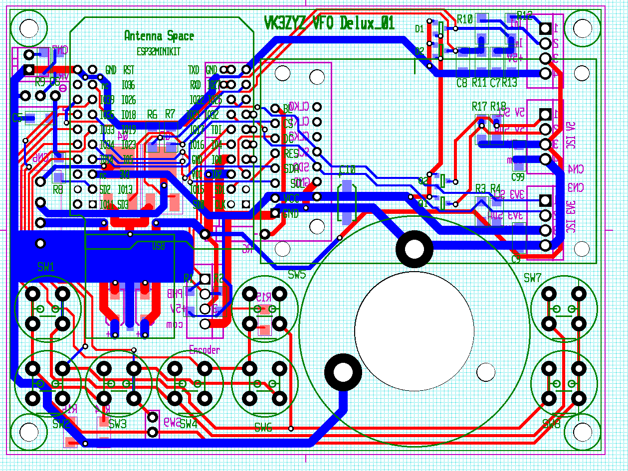

Now I am off for a coffee and a rest!
It will need to be checked.
Now I am off for a coffee and a rest!
V
VK3ZYZ
Guest
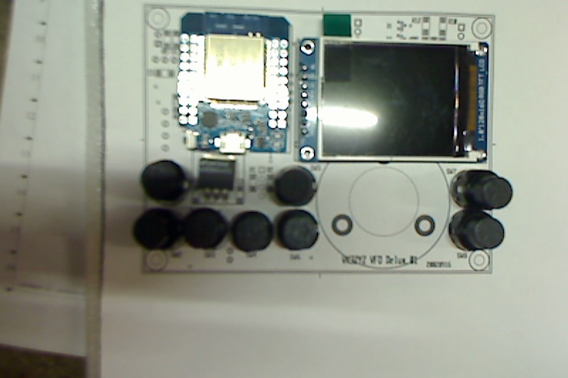
Well, I hope it is ok. I've just put in an order for 50 boards.
Fingers crossed! In a couple of weeks we will see.......
Sorry about the lousy picture.
Last edited by a moderator: