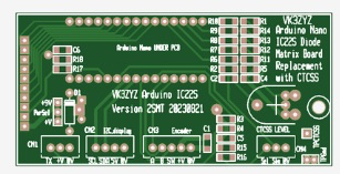
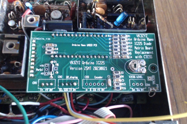
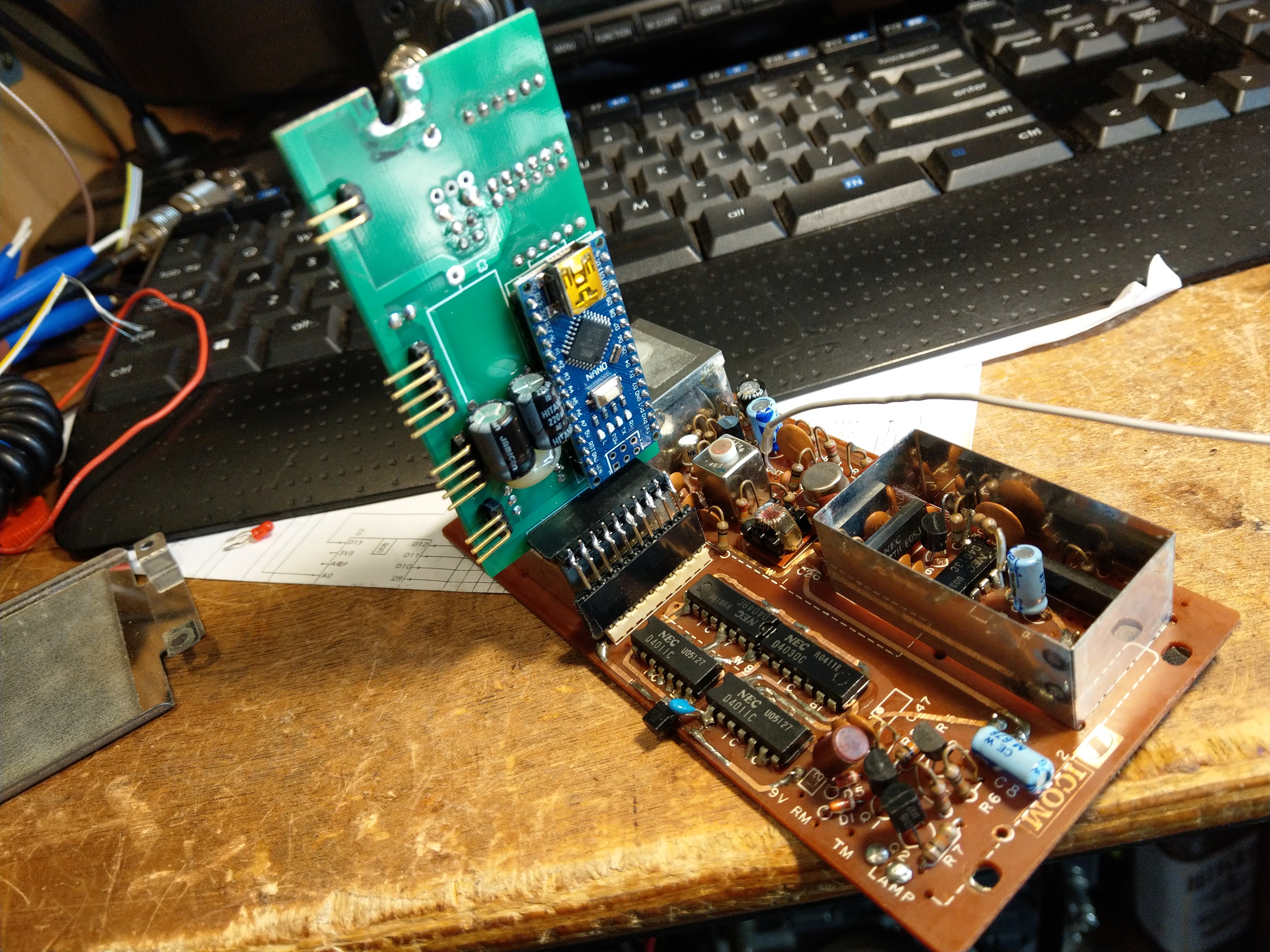
Acknowledging all the hard work done on the IC- 22S by Denys VK3ZYZ however the amount of modifications to the radio done to mitigate the Duplex issues was something that I wanted to overcome to keep all modifications to the radio to a bare minimum, in that the reversal to original form required as little to no work, simply fitting the matrix board and switch would return the radio to original condition.
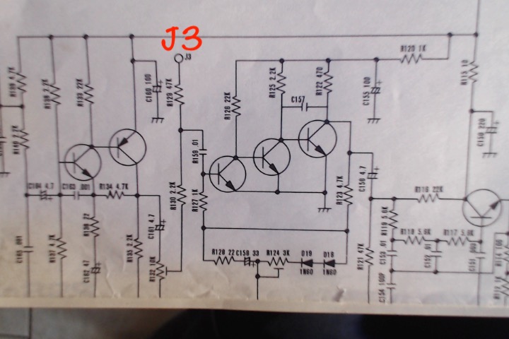
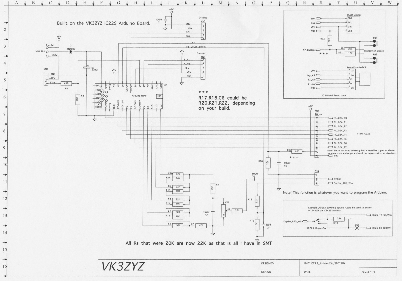
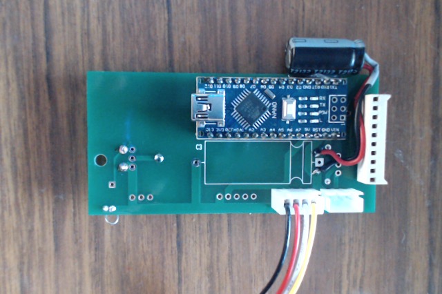
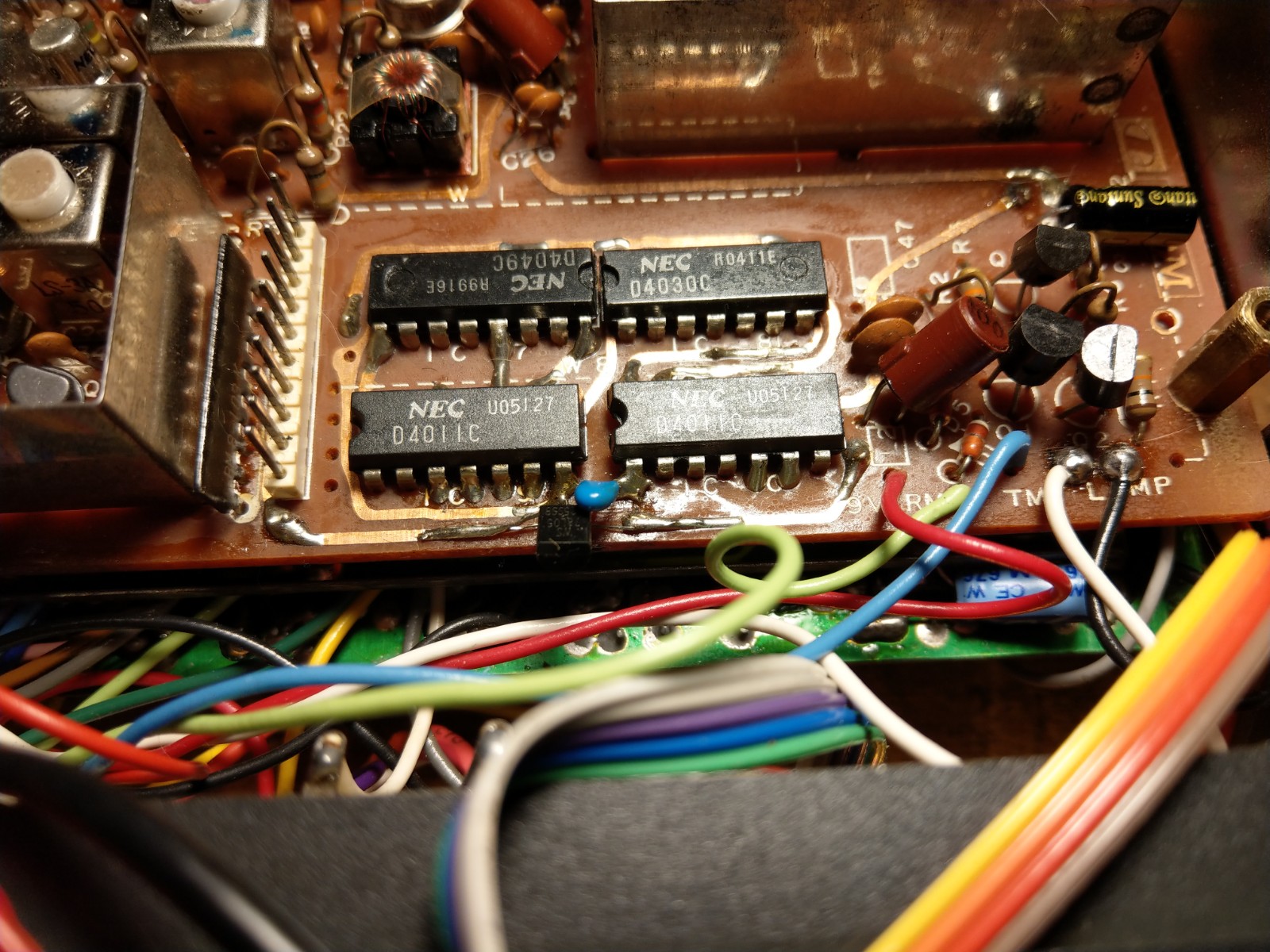
The first challenge was that the Arduino processor works on a 5 Volt logic level, this presented the issue that the radio Duplex logic IC’s run on a 9 volt rail so that the 0 to 5 was not sufficient to cause the circuit to work, fortunately in the manner that the voltage rail to the Duplex logic had been done made it possible to introduce a 5 V regulator to just run the Duplex circuit, now the Arduino could control the Duplex IC’s.
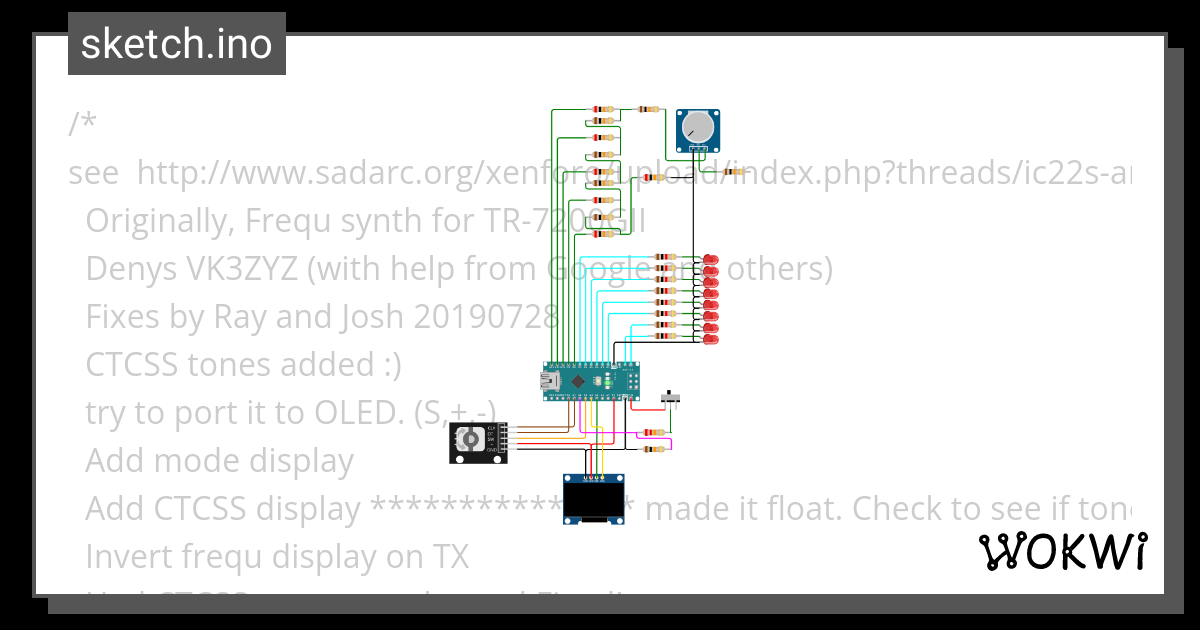
The radio control code was written from scratch but included some of the routines written by Denys namely the Rotary Encoder The CTCSS tone generation routines and some of the OLED Display structures.
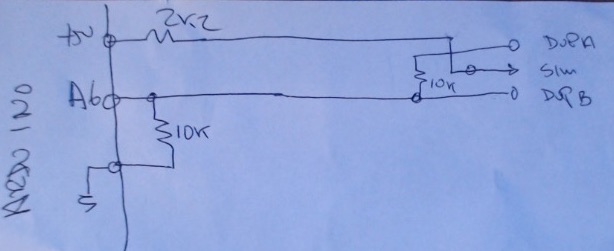
The first issue I was presented with is that one of the Arduino analogue pins is used for the Duplex switch ( A7) and assigned to be a digital pin, normally this is proper however on the Nano pins A6 and A7 are analogue only and not able to be reassigned.
The problem was solved by converting the switch analogue voltages on pin A7 to three logic states.
Duplex switch Voltage values returned in bit form (A/D conversion)
RX Duplex A Count 1023
TX Duplex A Count 12 to 14
Simplex A or B Count 0
RX Duplex B Count 160 to 161
TX Duplex B Count 1023
From the above values the three positions of the switch could be established.
Caveat – As much as I have provided for variations in radios that could have different values the above table it should cater for 99% of units by utilising value limits by testing if the value is between two limits, then the result is true.
The CTCSS code is selected by pushing the encoder knob, this changes the program to use the alternate mode in the void loop ()
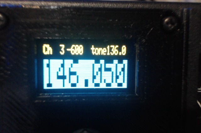
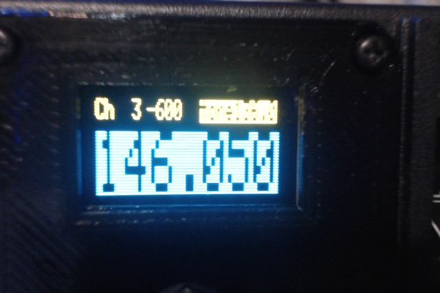
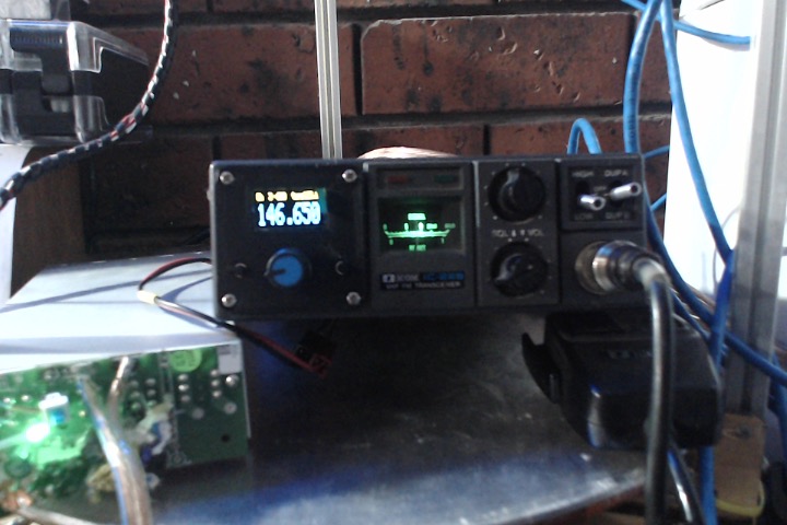
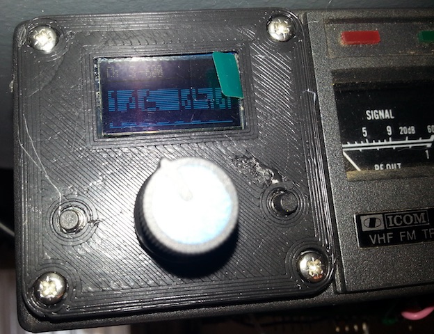
The CTCSS frequency is selected with a push of the encoder knob the “No Tone” indication will appear and the tone is off, turning the encoder knob clockwise selects the required CTCSS, pushing the encoder knob again returns to the frequency mode.
The activation of the Duplex switch will cause the frequency display to show what frequency the radio is receiving on.
The goal to be able to return the radio to stock condition is achieved even if the 5 Volt regulator is left in the radio.
Was a fun project, took many hours and presented several issues to overcome, doing so gave lots of gratification, no such thing as a problem only a solution.
Software releases
V2.2 Beta first release
V2.3 Fixes to CTCSS Logic, CTCSS only in TX mode, CTCSS Transmit only when when in Frequency mode
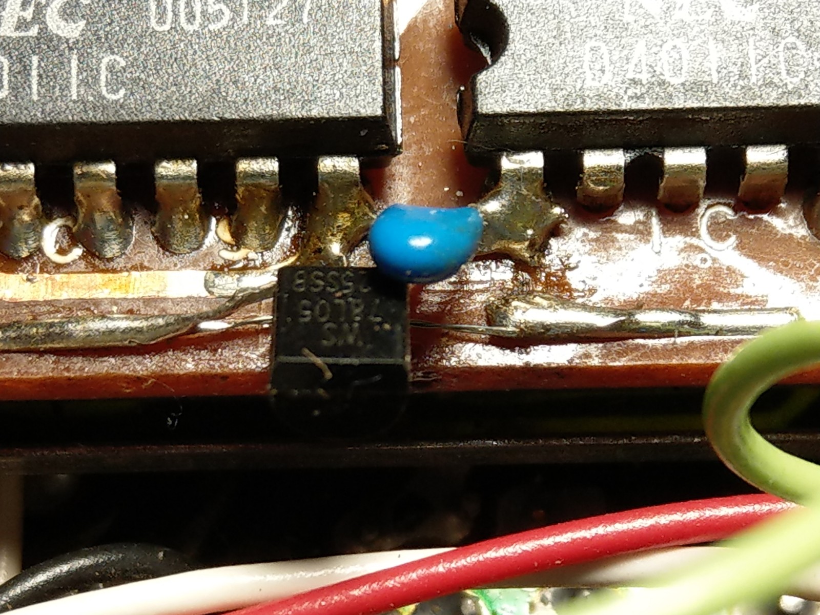
78L05 fitted to the PLL board to make the Logic compatible with the Arduino
Link to videos

 www.tinkercad.com

")