VK2RK
Active member
BillC I answer your post on this thread, on the other thread it's out of topic.
The problem of stability is more to do with man induced inaccuracy, or signal multipath that can be mitigated with a special antenna that rejects signal from low to the horizon satellites.
The effect is not large but can cause an error of +/- 3 PPB of just over 300 nS. signal drift.
In my first design I locked raising edge to raising edge using a very long time constant filter to reduce and mitigate for the above issues, realizing a better than +/- 3PPB worst case figure.
The drift was due to several factors not just the GPS path and introduced error, it also included the uneven division of the derived 10 KHz signal due to the internal oscillator of the Ublox GPS module that uses a 48 MHz that can't be evenly divided to10 KHz the effect introduces jitter.
However the original design obtained result was good enough for the intended purpose, but I was not happy with this I considered other solutions, one solution was to use of a processor to average out the drift having noted that the drift had a pattern to it, making it suitable for statistical processing resulting in a corrected Control Voltage.
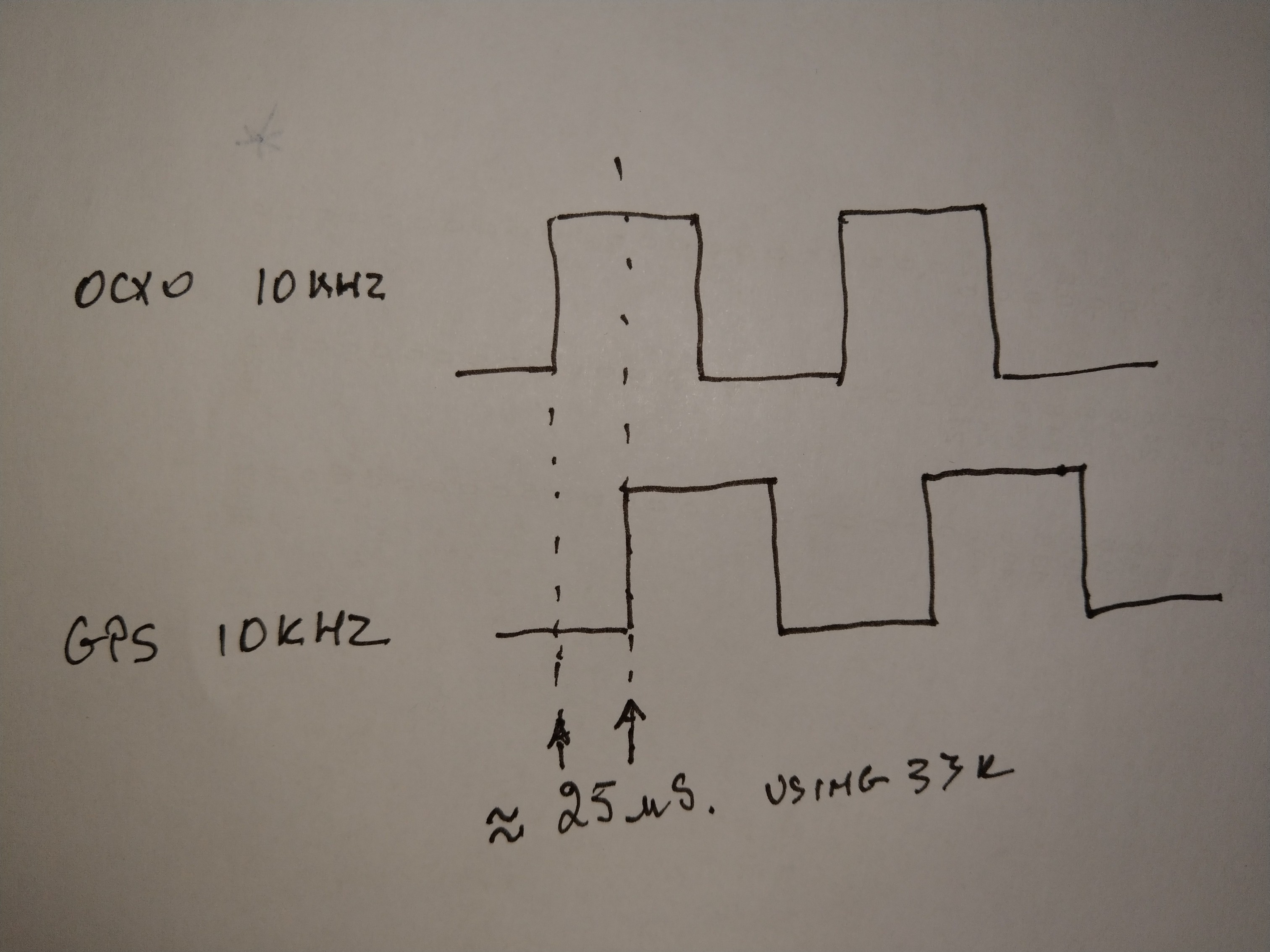
I am a KISS believer wanting a simpler solution in the end it was so simple that I don’t know why I did not think of it in first place, what I did was to shift the lock point from the edge to edge to 90 deg of each other, this was done by altering the PLL filter time constant causing the OCXO 10 KHz signal to be delayed by 25 uS, resulting in a control window that yielded more stable control voltage, any movement in GPS derived 10KHz as mentioned above has to move by more that 25 uS to cause a control voltage change, thus the stability improved achieving +/- 1.5 PPB worst case.
Any phase movement now is more due to noise (Allen Deviation).
As mentioned above what I could do in the future instead of an analogue solution is to digitize the Control voltage, then statistically derive a corrected voltage to apply to the OCXO, but it’s a degree of complexity that will yield a very small return when I am achieving better than
+/- 1.5PPB that is good enough for the purpose intended and very close to the Allen deviation noise.
The images below show the timing point for the PLL lock
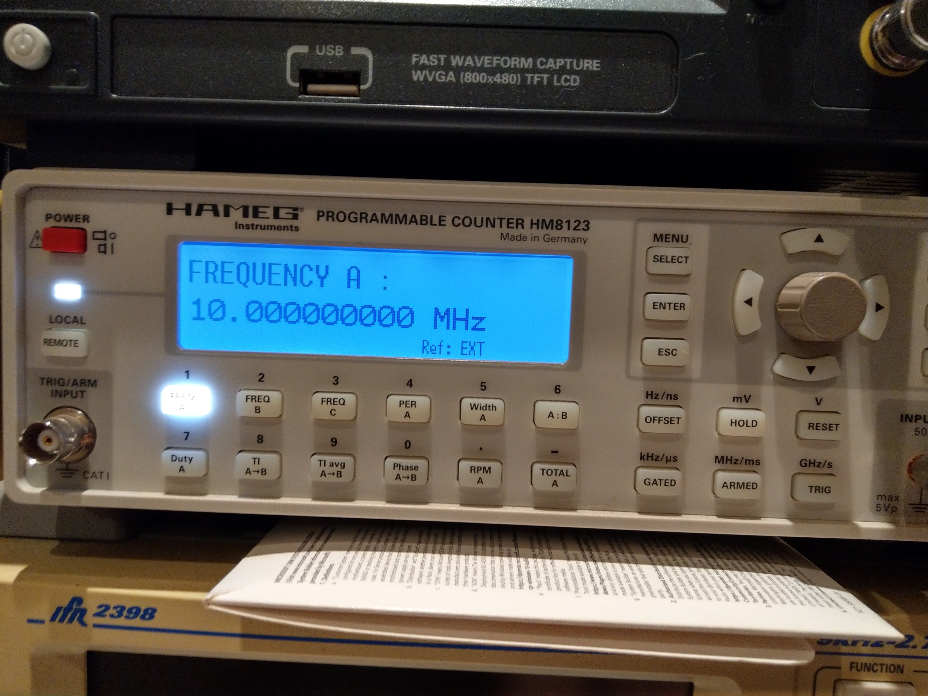
The counter shows a frequency using 30 Second sampling time that would include any jitter component, very very low been that of the OCXO.
Concluding the system error is better than +/- 1 x 10 Exp -9 (1nS.) Using a Trimble GPS as my reference.
Harmonics on the Square to Sine conversion better than -60dB
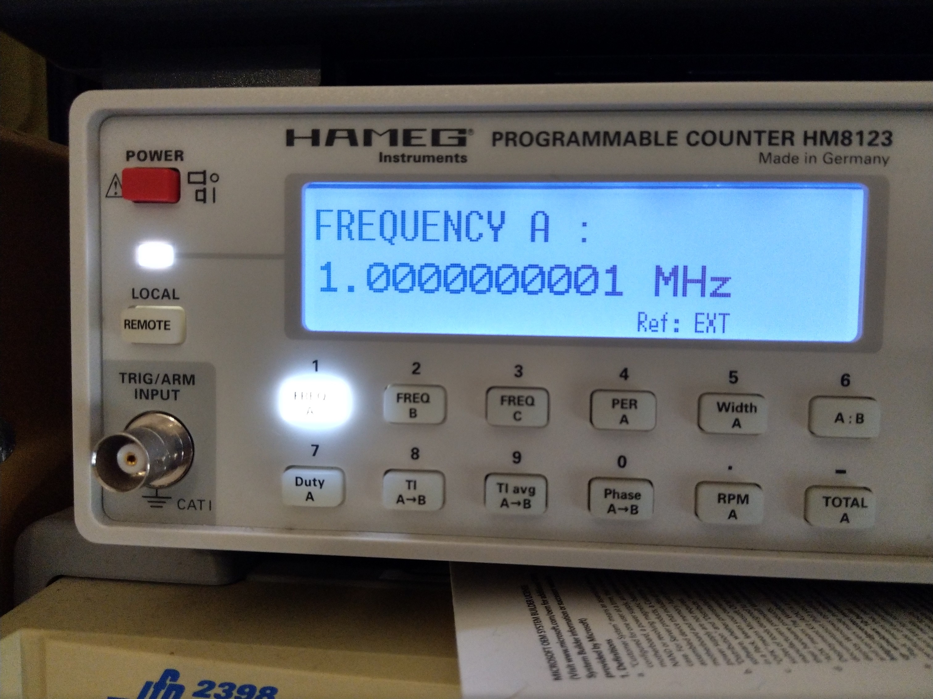
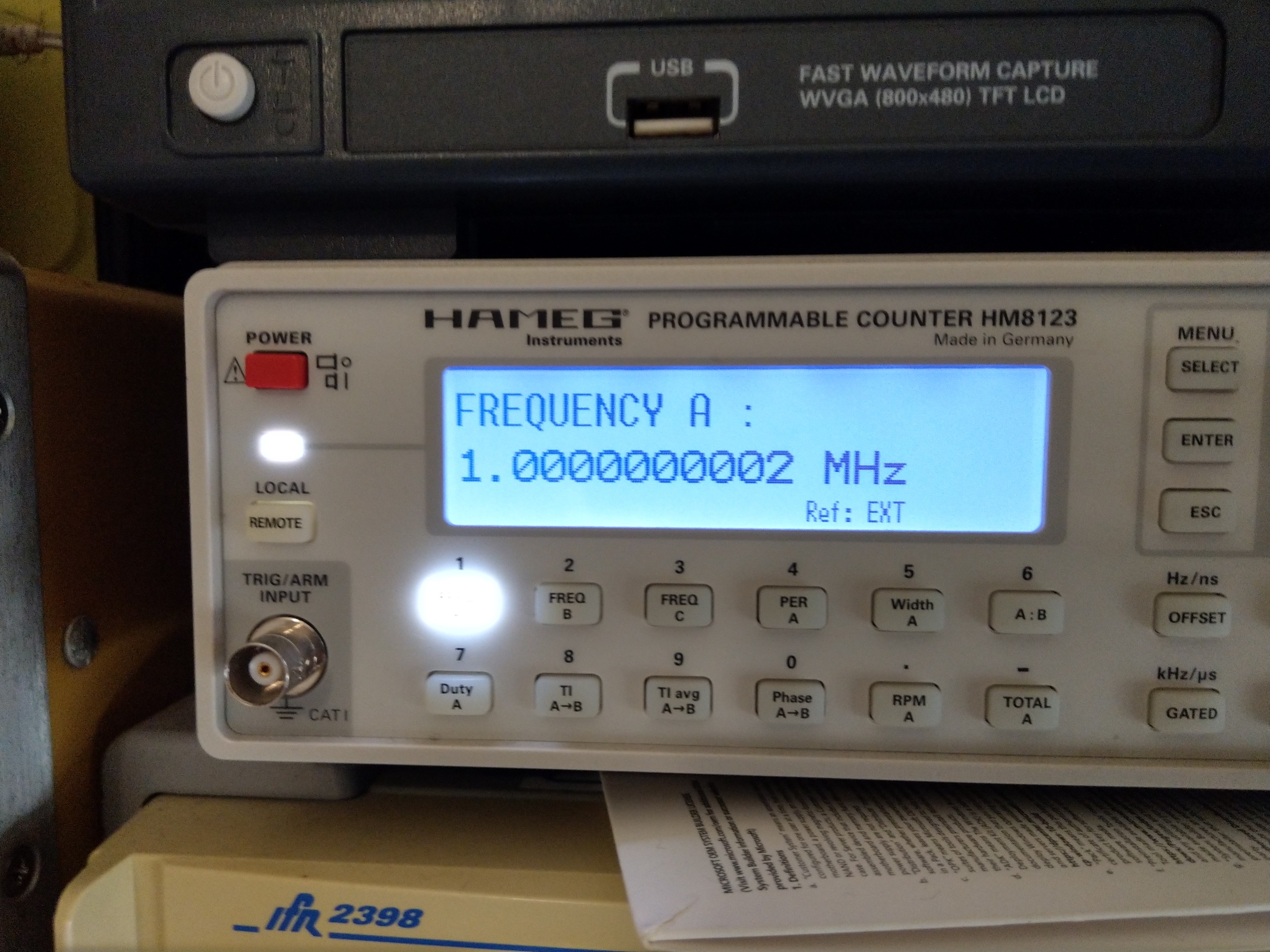
Note that the stability is measured at 10 MHz, if measured at 1 MHz I would show a ten times better specification as the error is further divided down. To measure to a lower degree of inaccuracy I would need to have a Cesium Beam reference for my counter (11 Digit resolution).
For a simple solution the result is really good, comparing it with the Leo Bodner device that all rave about, my design offers a more stable result.
Making a device that is frequency selectable as the Leo Bodner opens many problems in both stability and jitter, he uses a TXO that he divides to compare against his GPS reference, here we have the issue of uneven division causing jitter, some state they measure very low jitter on his device, this is not constant on his frequency coverage, some frequencies will have low jitter other will not, why I chose fixed frequencies that are even division of the OCXO.
I measured the GPS module signal I use (Note the same as the Leo Bodner device) The jitter at 1 KHz was no different to that obtained at 10 KHz, the PLL chip response at 10 KHz is a lot better than at 1 KHz so that is what I chose as others have done with their design, the idea was that more signal division taking place should result in a lower errors, this was not the case, it had more to do with the uneven division.
Measured at 10 MHz (Counter Gate Time 30 Seconds)
Error at 1 MHz +/- 0.3 PPB (3 x 10 Exp -10 Counter Gate Time 60 Seconds)
Hi Bill,Hi Rob, Just another thought, thinking about the accuracy of you GPS frequency standard I suppose you try to get maximum accuracy when sampling , such as within a degree or two of phase angle or equivalent range of a square wave to increase the sampling accuracy when digitizing / sampling a signal ,, just started to think about this, I know this is a simplistic idea , but is that approximately right ? I have built a sample and hold phase locked oscillator, the switching pulse has a 10 nano second rise time on a 1 Mhz time base so it will lock a VFO at 1Mhz intervals up to at least 100 Mhz . Would you like to see the circuit diagrams and some screen shots of waveforms and locking pulse etc ?
The problem of stability is more to do with man induced inaccuracy, or signal multipath that can be mitigated with a special antenna that rejects signal from low to the horizon satellites.
The effect is not large but can cause an error of +/- 3 PPB of just over 300 nS. signal drift.
In my first design I locked raising edge to raising edge using a very long time constant filter to reduce and mitigate for the above issues, realizing a better than +/- 3PPB worst case figure.
The drift was due to several factors not just the GPS path and introduced error, it also included the uneven division of the derived 10 KHz signal due to the internal oscillator of the Ublox GPS module that uses a 48 MHz that can't be evenly divided to10 KHz the effect introduces jitter.
However the original design obtained result was good enough for the intended purpose, but I was not happy with this I considered other solutions, one solution was to use of a processor to average out the drift having noted that the drift had a pattern to it, making it suitable for statistical processing resulting in a corrected Control Voltage.
I am a KISS believer wanting a simpler solution in the end it was so simple that I don’t know why I did not think of it in first place, what I did was to shift the lock point from the edge to edge to 90 deg of each other, this was done by altering the PLL filter time constant causing the OCXO 10 KHz signal to be delayed by 25 uS, resulting in a control window that yielded more stable control voltage, any movement in GPS derived 10KHz as mentioned above has to move by more that 25 uS to cause a control voltage change, thus the stability improved achieving +/- 1.5 PPB worst case.
Any phase movement now is more due to noise (Allen Deviation).
As mentioned above what I could do in the future instead of an analogue solution is to digitize the Control voltage, then statistically derive a corrected voltage to apply to the OCXO, but it’s a degree of complexity that will yield a very small return when I am achieving better than
+/- 1.5PPB that is good enough for the purpose intended and very close to the Allen deviation noise.
The images below show the timing point for the PLL lock
The counter shows a frequency using 30 Second sampling time that would include any jitter component, very very low been that of the OCXO.
Concluding the system error is better than +/- 1 x 10 Exp -9 (1nS.) Using a Trimble GPS as my reference.
Harmonics on the Square to Sine conversion better than -60dB
Note that the stability is measured at 10 MHz, if measured at 1 MHz I would show a ten times better specification as the error is further divided down. To measure to a lower degree of inaccuracy I would need to have a Cesium Beam reference for my counter (11 Digit resolution).
For a simple solution the result is really good, comparing it with the Leo Bodner device that all rave about, my design offers a more stable result.
Making a device that is frequency selectable as the Leo Bodner opens many problems in both stability and jitter, he uses a TXO that he divides to compare against his GPS reference, here we have the issue of uneven division causing jitter, some state they measure very low jitter on his device, this is not constant on his frequency coverage, some frequencies will have low jitter other will not, why I chose fixed frequencies that are even division of the OCXO.
I measured the GPS module signal I use (Note the same as the Leo Bodner device) The jitter at 1 KHz was no different to that obtained at 10 KHz, the PLL chip response at 10 KHz is a lot better than at 1 KHz so that is what I chose as others have done with their design, the idea was that more signal division taking place should result in a lower errors, this was not the case, it had more to do with the uneven division.
Measured at 10 MHz (Counter Gate Time 30 Seconds)
Error at 1 MHz +/- 0.3 PPB (3 x 10 Exp -10 Counter Gate Time 60 Seconds)
Last edited:
Hi Rob Thanks again for those explanations, I have read it all several times , 48 MHz would seem to be a difficult choice of frequency to work to, with no easy division . I wonder why 48 MHz was chosen for the GPS unit, it does not seem to divide down to any easily usable number. I am fairly sure that my sample and hold phase locked VFO does not jitter because the VFO is designed to lock at the harmonics which are integer multiples of the 1MHz crystal reference oscillator. I have looked at the waveforms of the locking process and it appears to achieve lock in the first 90 deg. [rising edge] as it were . Of course the crystal reference oscillator could drift, and the VFO would follow that drift, but when used in a receiver a small amount of drift is not really a problem as it can be accomodated by passband of the IF stage . But digital must be spot on Hey? Cheers..
VK2RK
Active member
Hi Bill, I understand, if you remember I had a look at your design some time ago at the club, well done it is a clever solution.the crystal reference oscillator could drift, and the VFO would follow that drift, but when used in a receiver a small amount of drift is not really a problem as it can be accomodated by passband of the IF stage . But digital must be spot on Hey? Cheers..
In my case the design is intended as a sub standard reference providing the most common frequencies 10 MHz, 5 MHz and 1 MHz commonly found on instruments, along with the concept of as cheap as possible for those building the project.
If I was to make a tunable device I would use another approach. With all frequency synthesis systems to rely on just division will rear the ugly head of uneven (Non Integer) division, so that in many designs they use a mixing concept that of generating those parts and mixing to the final frequency, this been an analog process, unlike what I have created that is purely digital with filtering at the end of the process, note that been digital I need not be concerned with temperature aside that of the OCXO, only when using the OCXO without GPS reference that temperature did play a role in the stability of the control voltage thus the resultant frequency.
Different problems require differing solutions.
VK2RK
Active member
I bought one along to the club that I had opened up when I did the demo of the unit I designed.Just for interest, this is what is inside one of those oscillators...
VK2RK
Active member
The GPS referenced frequency sub-standard I designed has now been running continuously for just on a year.
The device has retained design specification all this time with an accuracy of +/- 0.001 Hz @ 10 MHz without using special timing antenna. The manner that the PLL lock is obtained results in very stable frequency mitigating signal multipath and OCXO jitter (If any)
The aging of the OCXO has further helped in the obtained stability