VK2RK
Active member
DC Voltage conditioner
One of the problems when a two way radio is powered by an external power supply is the voltage drop at the radio due to the resistance in the power cable used.
Using my ICOM IC7610 with the factory supplied DC cable, in RX mode the DC voltage at the radio input terminal was 13.5 Volts, when in TX mode with maximum power (110 Watts) the current draw was 16 Amps, the voltage dropped to 12.9 Volts, calculating the combined positive and negative wire resistance of the cable results in 0.0375 Ohms R = (13.5-12.9)/16 = 0.0375 Ohms
This resistance does not seem to be a lot, however in TX mode the voltage drop is 600 mV dropping the input power from 216 Watts to 206.4 Watts a loss of approximately 10 Watts.
Input Power of 13.5 x 16 = 216.0 Watts
Input Power of 12.9 x 16 = 206.4 Watts
In a simplistic explanation, the action of the ALC that controls the RF output power will accommodate this power loss, however it decreases the efficiency of the Power Amplifier, further the SSB RF peaks will be reduced even when the ALC compensates for the lower power, Note that ALC response has hysteresis such that the power peak maximum value has to occur before its controlled, therefore having the lowest possible voltage drop at the radio DC input improves the SSB peak response along with the efficiency of the RF finals that will reduce the current draw from the power supply.
Another way to look at this is to say that the power supply has to offer the lowest possible impedance to the radio, delivering peak currents without a voltage loss, The lower the impedance the less voltage loss.
In a base station installation the effect can mostly be eliminated by having the power supply located as close as possible to the radio making the DC cable short, not possible in a mobile installation.
The rule is basically this, keep the resistance of the DC source to the load as low as possible either by increasing the diameter of the cable wire or by reducing the length of the cable.
There is another way, that of using a super capacitor placed as close as possible to the radio DC input, such that the DC source impedance is so low that can supply very large peak currents and minimal voltage drop, I say minimal as there always be some resistance be it in a fuse or length of wire, but if very small so small it can be ignored.
Using a super capacitor presents some problems.
a) Initial inrush current is very high only limited by the charging source.
b) The stored charge is very high requiring proper safe handling (Will melt wire)
It’s not as simple as it may appear to just add a super capacitor, the inrush current must be limited allowing the capacitor to charge to a voltage value such that the charging current is within the range of the power supply capacity, as the capacitor voltage raises, inversely the required current reduces.
When dealing with capacitance values of over a Farad the time to charge the device is considerably long
largely controlled by the available current from the power source.
Understanding that the initial charge of the capacitor must be controlled with safety keeping in mind that we are dealing with metal melting currents, ignoring this can result in damage to the power supply or worst. To give some prospective the stored energy is calculated E = CxVxV/2
Thus 16.6 x 13.82 x 13.82 = 3161.304 Joules This is a huge number that needs to be respected, converting to Coulombs (1 Joule = 1 Coulomb) The definition of a coulomb is 1 Amp per second so having 3161.304 Joules stored can deliver in an instance almost infinite current only limited by the resistance in the circuit.
Handle super capacitors as you would a fully charged car battery.
Having provided the required protections the device can be placed as close as possible to the radio
The cable voltage drop due to the Resistance losses is cancelled out by the action of the capacitor.
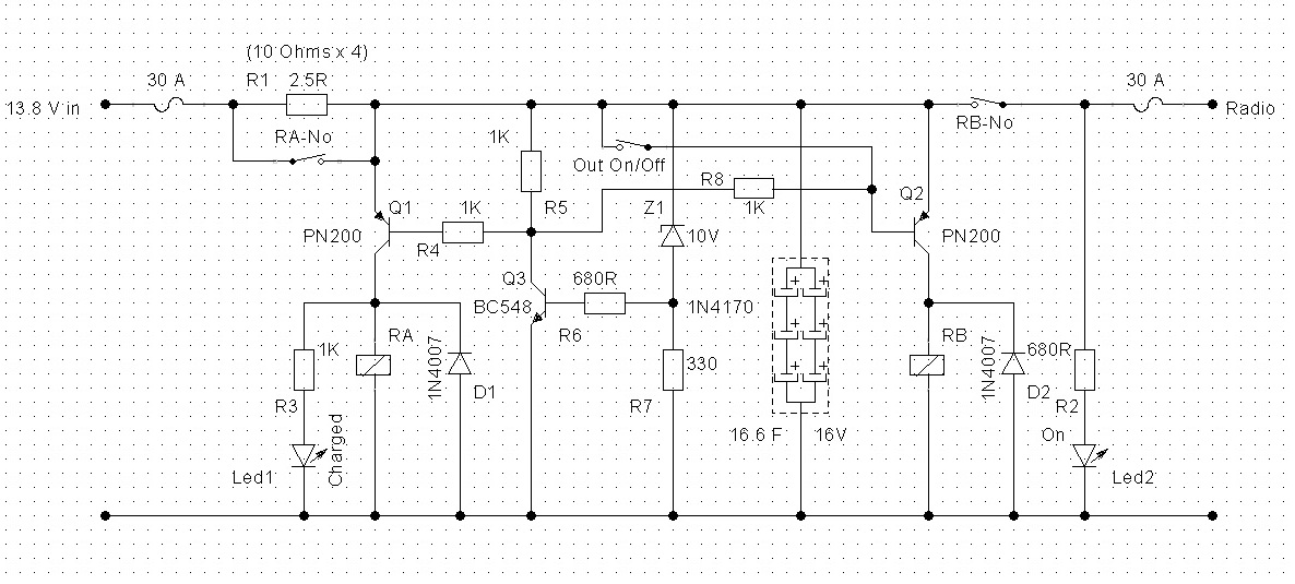
Circuit Operation
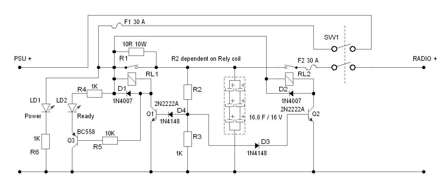
Fully discharged condition:
1/ When SW1 is operated DC current flow from the power supply and charge the super capacitor via R1
limiting the inrush current. At this time RL2 is Normally Open providing no power to the radio.
2/ R2 and R3 forms an voltage divider, (Note the R2 and R3 values are just an estimation requiring knowledge of the coil resistance for proper value selection) When the voltage at the super capacitor reaches 11.2 Volts
Transistor Q1 and Q2 saturate, energising RL1 connecting the DC input directly across the supercapacitor that then completes the charge topping up to equal that of the power supply output voltage at the same time RL2 closes powering the radio.
LD2 indicates that the Super capacitor is fully charged, when Q1 is saturated Q3 also saturates illuminating the LED.
3/ LD1 has a dual purpose, indicate that the unit is connected to the DC power supply and residual charge when in a off condition, the capacitor is bled off via R1, R2 and R3 (Discharge path)
Note that the discharge process takes a long time, so don’t short the output or the F2 fuse will blow.
F1 fuse protects the power supply from any shorts upstream of it.
Partially Charged condition:
The above operation remains the same but for the charge time that is dependent on the residual charge of the capacitor. To fully discharged the capacitor the time is calculated by using the Time constant formula
T = R x C x 6 Thus 9 K x 16.6 x 6 = 10.375 Days
If you use the radio once per day the charging process is considerably shortened to almost nothing.
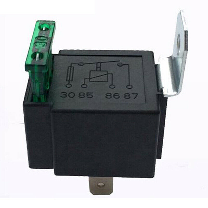
Chosen relay
Obtained from eBay, Automotive 30 AMP with built fuse making construction simpler in not having to have separate fuse holders.
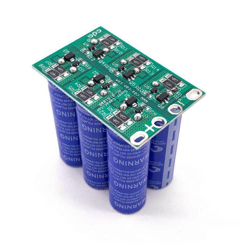
Super Capacitor Sourced eBay
Note the above is a theoretical design not yet prototyped.
The concept is to have an extremely low power supply source impedance that offers peak currents as required by the transmitter with no limitations, efficiency of both power supply and radio are increased.
VK2RK
One of the problems when a two way radio is powered by an external power supply is the voltage drop at the radio due to the resistance in the power cable used.
Using my ICOM IC7610 with the factory supplied DC cable, in RX mode the DC voltage at the radio input terminal was 13.5 Volts, when in TX mode with maximum power (110 Watts) the current draw was 16 Amps, the voltage dropped to 12.9 Volts, calculating the combined positive and negative wire resistance of the cable results in 0.0375 Ohms R = (13.5-12.9)/16 = 0.0375 Ohms
This resistance does not seem to be a lot, however in TX mode the voltage drop is 600 mV dropping the input power from 216 Watts to 206.4 Watts a loss of approximately 10 Watts.
Input Power of 13.5 x 16 = 216.0 Watts
Input Power of 12.9 x 16 = 206.4 Watts
In a simplistic explanation, the action of the ALC that controls the RF output power will accommodate this power loss, however it decreases the efficiency of the Power Amplifier, further the SSB RF peaks will be reduced even when the ALC compensates for the lower power, Note that ALC response has hysteresis such that the power peak maximum value has to occur before its controlled, therefore having the lowest possible voltage drop at the radio DC input improves the SSB peak response along with the efficiency of the RF finals that will reduce the current draw from the power supply.
Another way to look at this is to say that the power supply has to offer the lowest possible impedance to the radio, delivering peak currents without a voltage loss, The lower the impedance the less voltage loss.
In a base station installation the effect can mostly be eliminated by having the power supply located as close as possible to the radio making the DC cable short, not possible in a mobile installation.
The rule is basically this, keep the resistance of the DC source to the load as low as possible either by increasing the diameter of the cable wire or by reducing the length of the cable.
There is another way, that of using a super capacitor placed as close as possible to the radio DC input, such that the DC source impedance is so low that can supply very large peak currents and minimal voltage drop, I say minimal as there always be some resistance be it in a fuse or length of wire, but if very small so small it can be ignored.
Using a super capacitor presents some problems.
a) Initial inrush current is very high only limited by the charging source.
b) The stored charge is very high requiring proper safe handling (Will melt wire)
It’s not as simple as it may appear to just add a super capacitor, the inrush current must be limited allowing the capacitor to charge to a voltage value such that the charging current is within the range of the power supply capacity, as the capacitor voltage raises, inversely the required current reduces.
When dealing with capacitance values of over a Farad the time to charge the device is considerably long
largely controlled by the available current from the power source.
Understanding that the initial charge of the capacitor must be controlled with safety keeping in mind that we are dealing with metal melting currents, ignoring this can result in damage to the power supply or worst. To give some prospective the stored energy is calculated E = CxVxV/2
Thus 16.6 x 13.82 x 13.82 = 3161.304 Joules This is a huge number that needs to be respected, converting to Coulombs (1 Joule = 1 Coulomb) The definition of a coulomb is 1 Amp per second so having 3161.304 Joules stored can deliver in an instance almost infinite current only limited by the resistance in the circuit.
Handle super capacitors as you would a fully charged car battery.
Having provided the required protections the device can be placed as close as possible to the radio
The cable voltage drop due to the Resistance losses is cancelled out by the action of the capacitor.
Circuit Operation
Fully discharged condition:
1/ When SW1 is operated DC current flow from the power supply and charge the super capacitor via R1
limiting the inrush current. At this time RL2 is Normally Open providing no power to the radio.
2/ R2 and R3 forms an voltage divider, (Note the R2 and R3 values are just an estimation requiring knowledge of the coil resistance for proper value selection) When the voltage at the super capacitor reaches 11.2 Volts
Transistor Q1 and Q2 saturate, energising RL1 connecting the DC input directly across the supercapacitor that then completes the charge topping up to equal that of the power supply output voltage at the same time RL2 closes powering the radio.
LD2 indicates that the Super capacitor is fully charged, when Q1 is saturated Q3 also saturates illuminating the LED.
3/ LD1 has a dual purpose, indicate that the unit is connected to the DC power supply and residual charge when in a off condition, the capacitor is bled off via R1, R2 and R3 (Discharge path)
Note that the discharge process takes a long time, so don’t short the output or the F2 fuse will blow.
F1 fuse protects the power supply from any shorts upstream of it.
Partially Charged condition:
The above operation remains the same but for the charge time that is dependent on the residual charge of the capacitor. To fully discharged the capacitor the time is calculated by using the Time constant formula
T = R x C x 6 Thus 9 K x 16.6 x 6 = 10.375 Days
If you use the radio once per day the charging process is considerably shortened to almost nothing.
Chosen relay
Obtained from eBay, Automotive 30 AMP with built fuse making construction simpler in not having to have separate fuse holders.
Super Capacitor Sourced eBay
Note the above is a theoretical design not yet prototyped.
The concept is to have an extremely low power supply source impedance that offers peak currents as required by the transmitter with no limitations, efficiency of both power supply and radio are increased.
VK2RK
Last edited: