V
VK2RK
Guest
I blame VK3TJS for this, I was quite happy with my inverted V fan dipole for 80 and 40, but as I have been looking into off center fed dipoles, trying to understand the common mode current issues some are having, I thought why not build one, it could be a better alternative to the fan dipole currently in use by me.
The OCF antenna is an evolution of a Windom antenna, it differs in that its coax fed via a BALUN, all other operation principles are the same, the feed point is moved from the center point to give an impedance of 200 Ohms, thus the harmonics of the higher frequencies will give the same impedance, making the antenna a multi-band antenna, However the down side is that at the higher frequencies the propagation pattern will no longer be that of a dipole, with many lobes.
There is modelling on the web that shows this.
The first thing that struck me is that the quality of the BALUN is very important in obtaining a constant match to both the fundamental and the harmonics, ideally the matching component (BALUN) must have a flat response, this to provide the 4:1 transformation to 50 Ohms. BUT a big but, this point will exhibit a very reactive value that many show as 200 Ohms, none of the research I have done shows the complex value eg( 200 J-something) so the conclusion is that I am not going to spend time calculating this as there exists many unknowns that vary considerably with external factors, thus the assumption is that of 200 Ohms reactive, ( Here is why we have the common mode current issue. )
A transmission line or system, (I include the BALUN) at the feed point we expect to see that the voltage and current to be in phase, but a big BUT the point chosen is not going to give us a pure resistivity load, by the nature that its not at the center, its phase difference is going to be very different to a center fed dipole, take this a bit further and the resistivity value of the transmission line will only be so at the exit of the cable not at the connection to the dipole.
With an off center fed dipole this situation is worst, so it can be expected to have larger common mode currents, purely due to the reactive (J) values of the complex impedance.
Concluding, a very flat responding BALUN is a must to reduce and keep common mode currents to a minimum, but this is not easy to achieve.
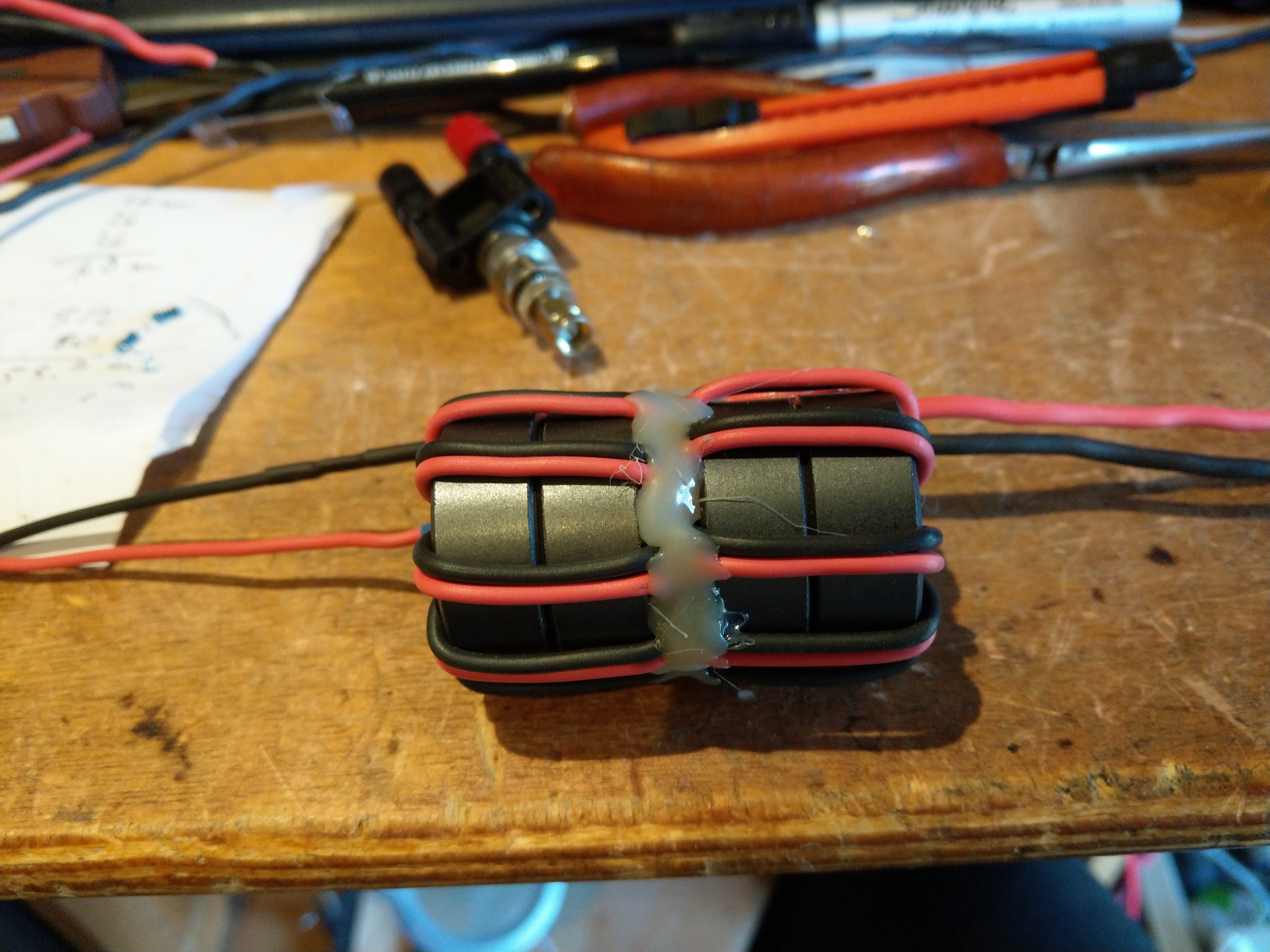
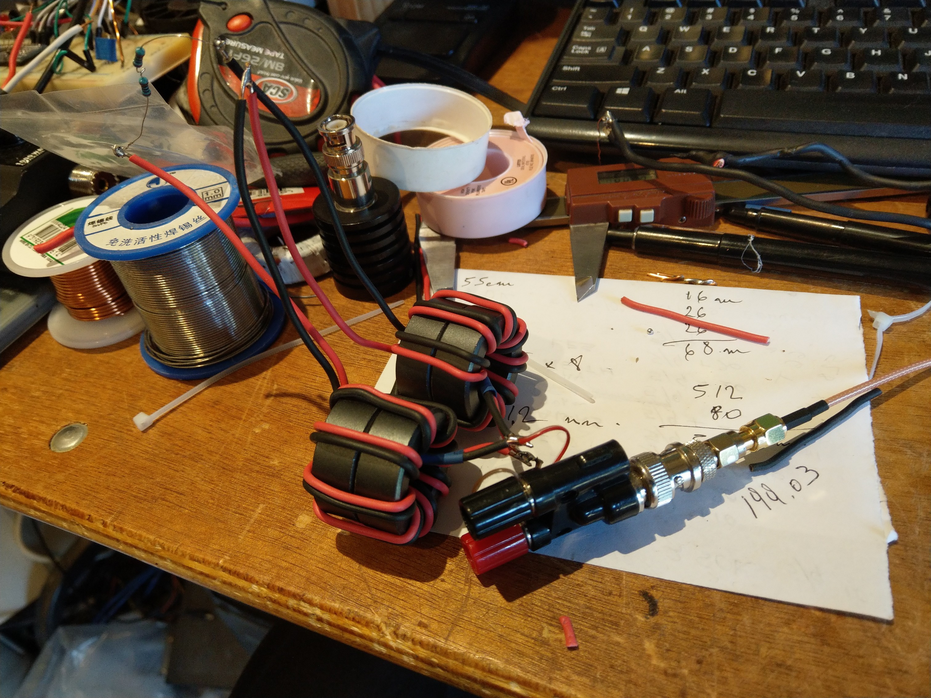
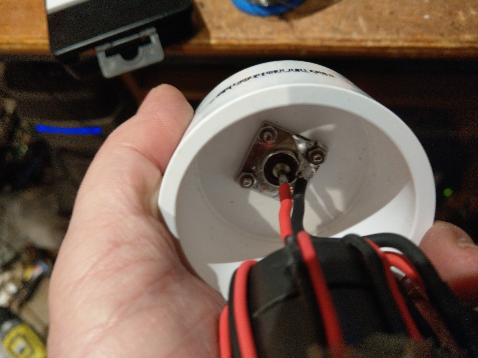
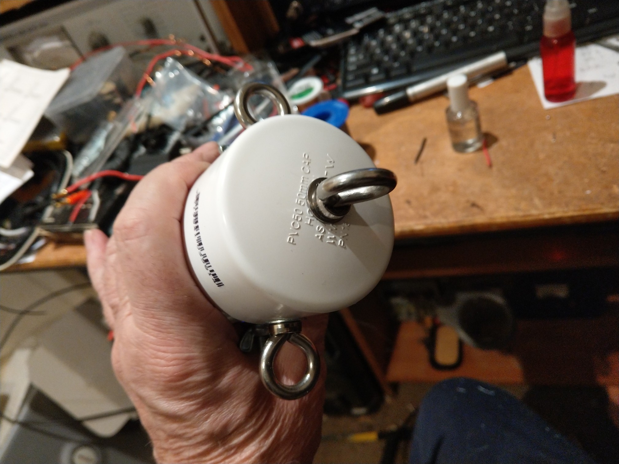
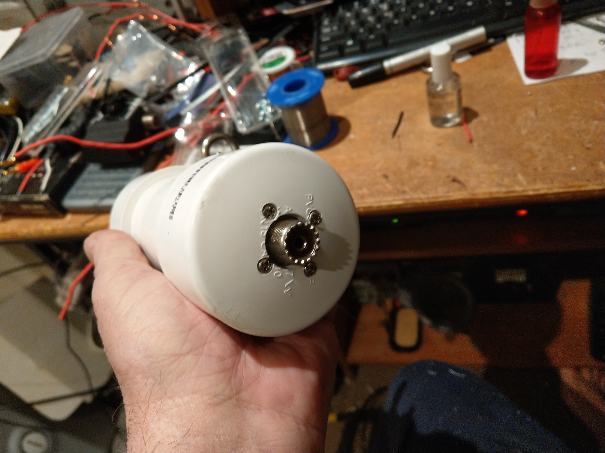
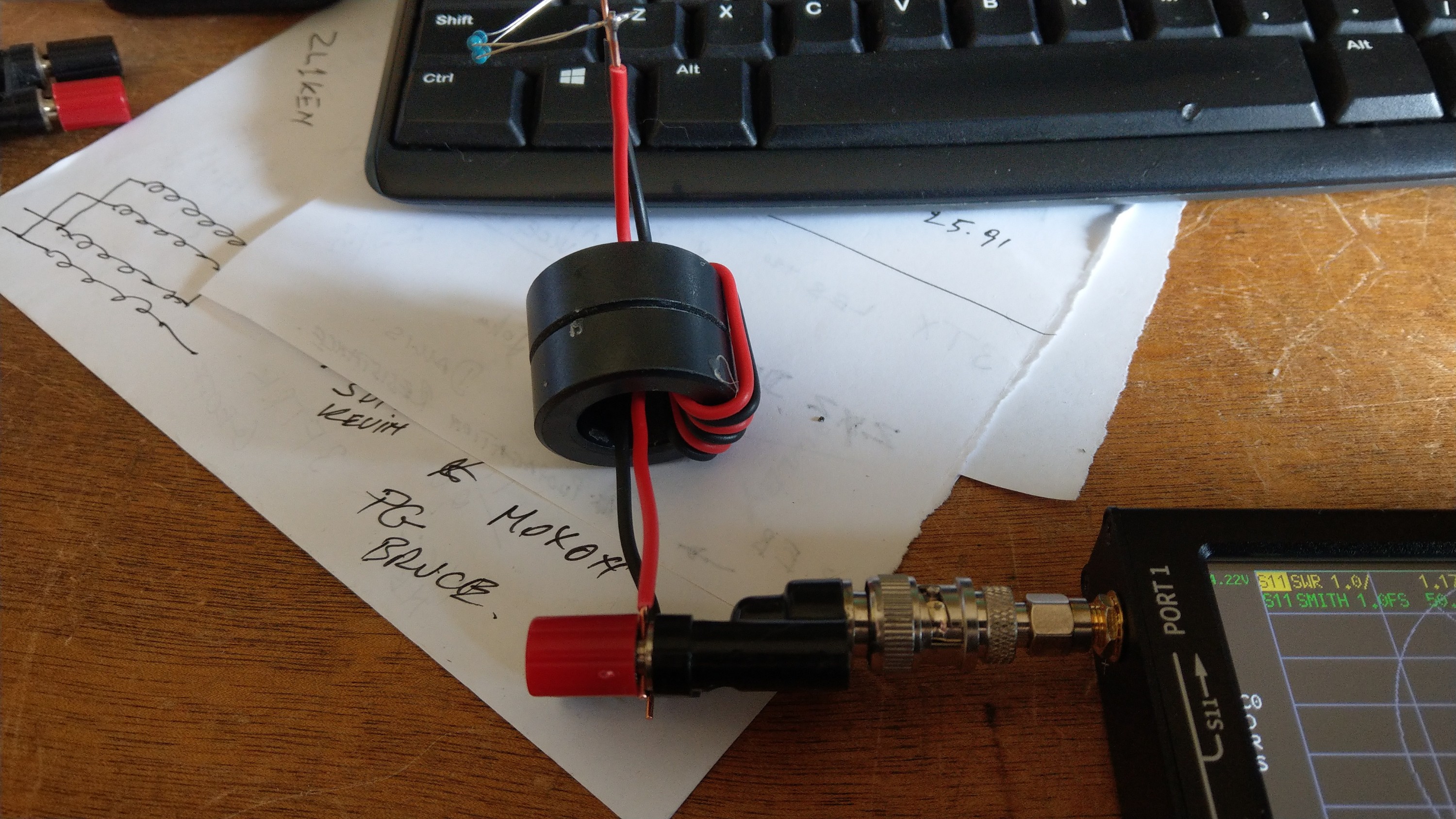
I decided to construct a 4:1 BALUN dual core, here I would like some comments from those that may have already been down this road I am travelling on.
BALUN Construction:
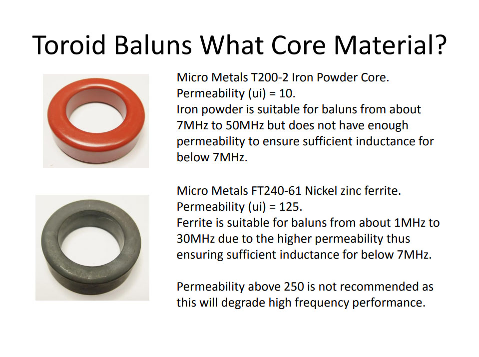
Core T200-2 (Brown Colour) Happen to have these in my junk box
Construction is that of Common Mode Choke
8 turns total 4 by 4 opposite phase
Output in series, input in parallel
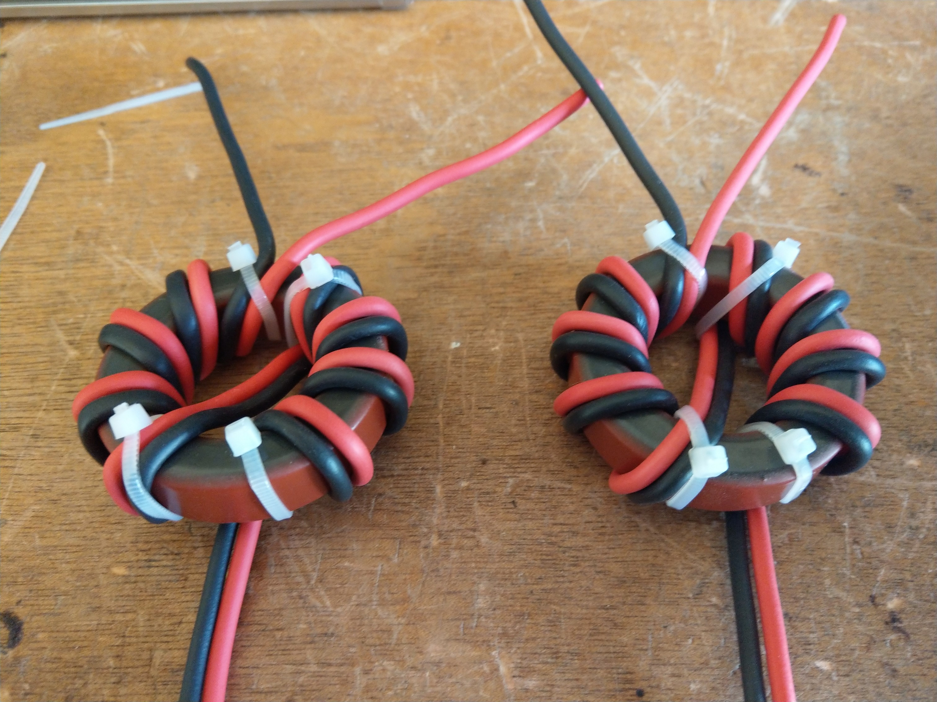
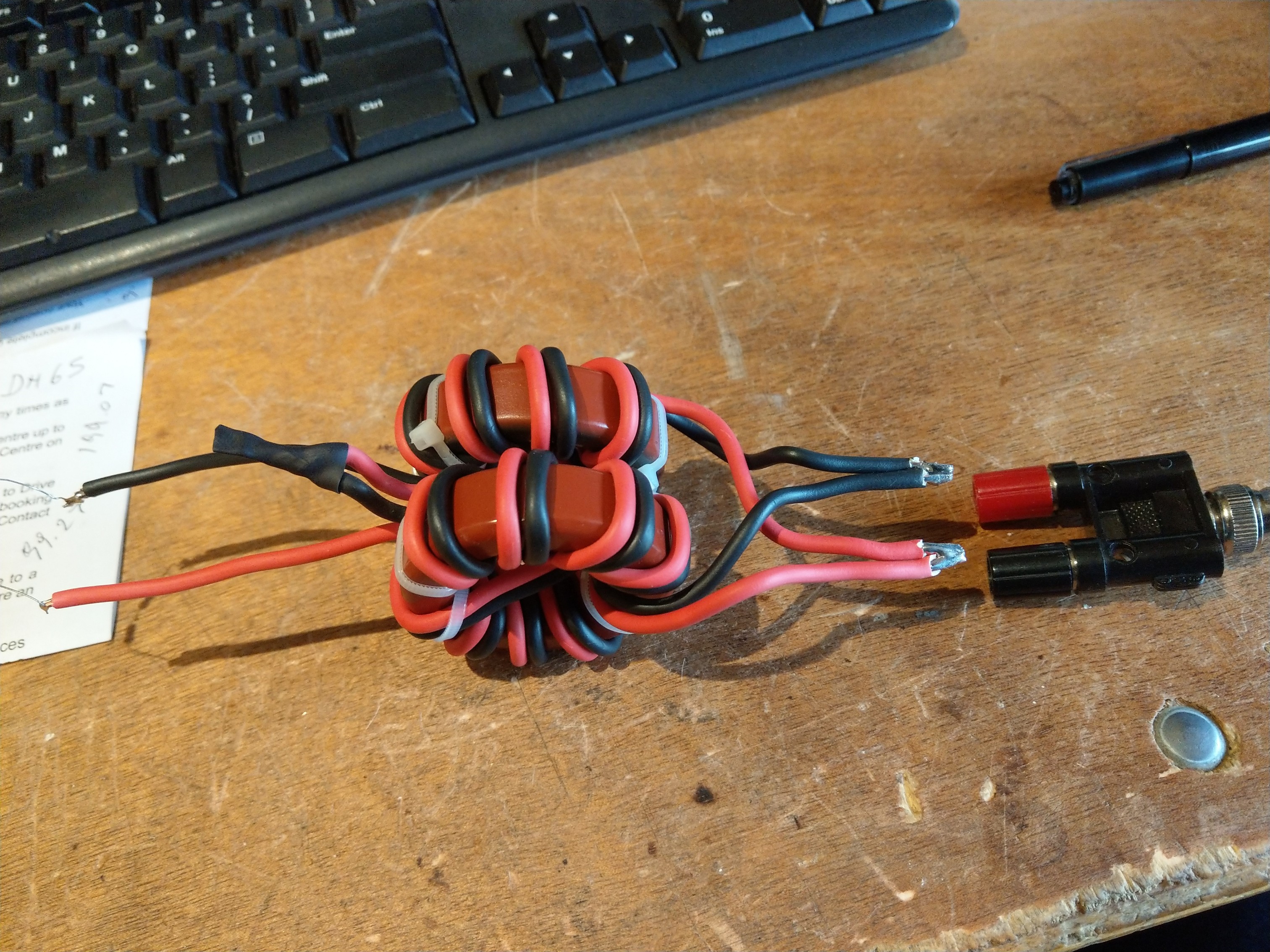
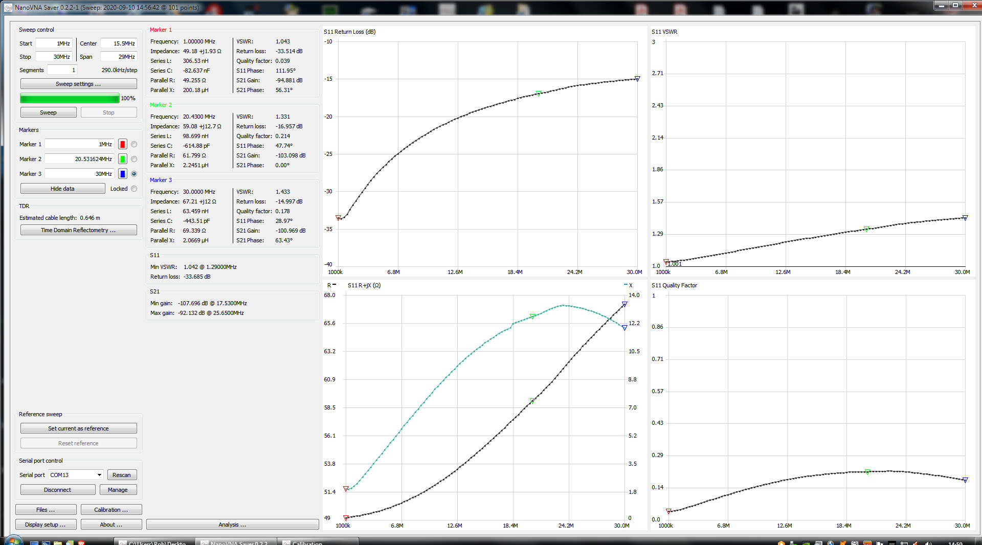
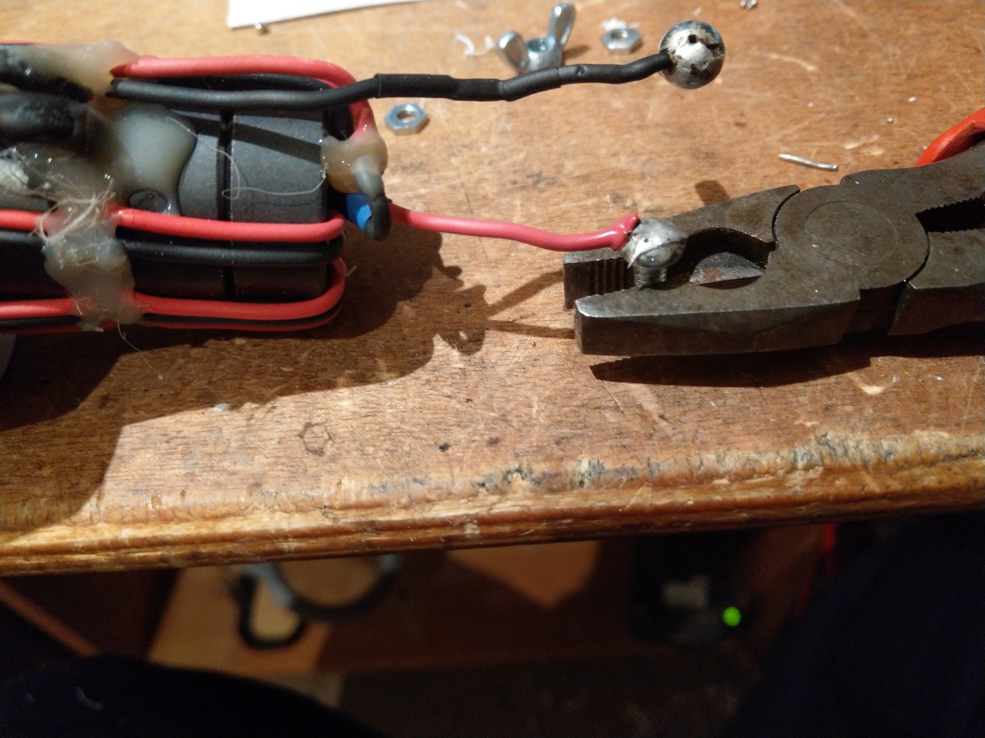
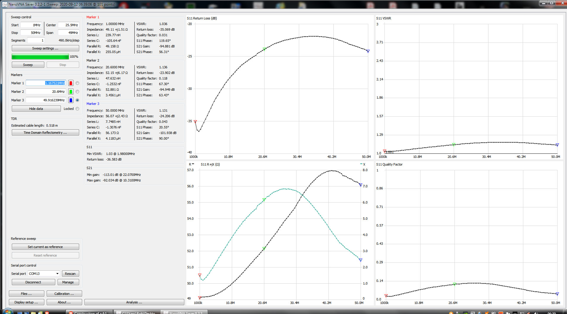
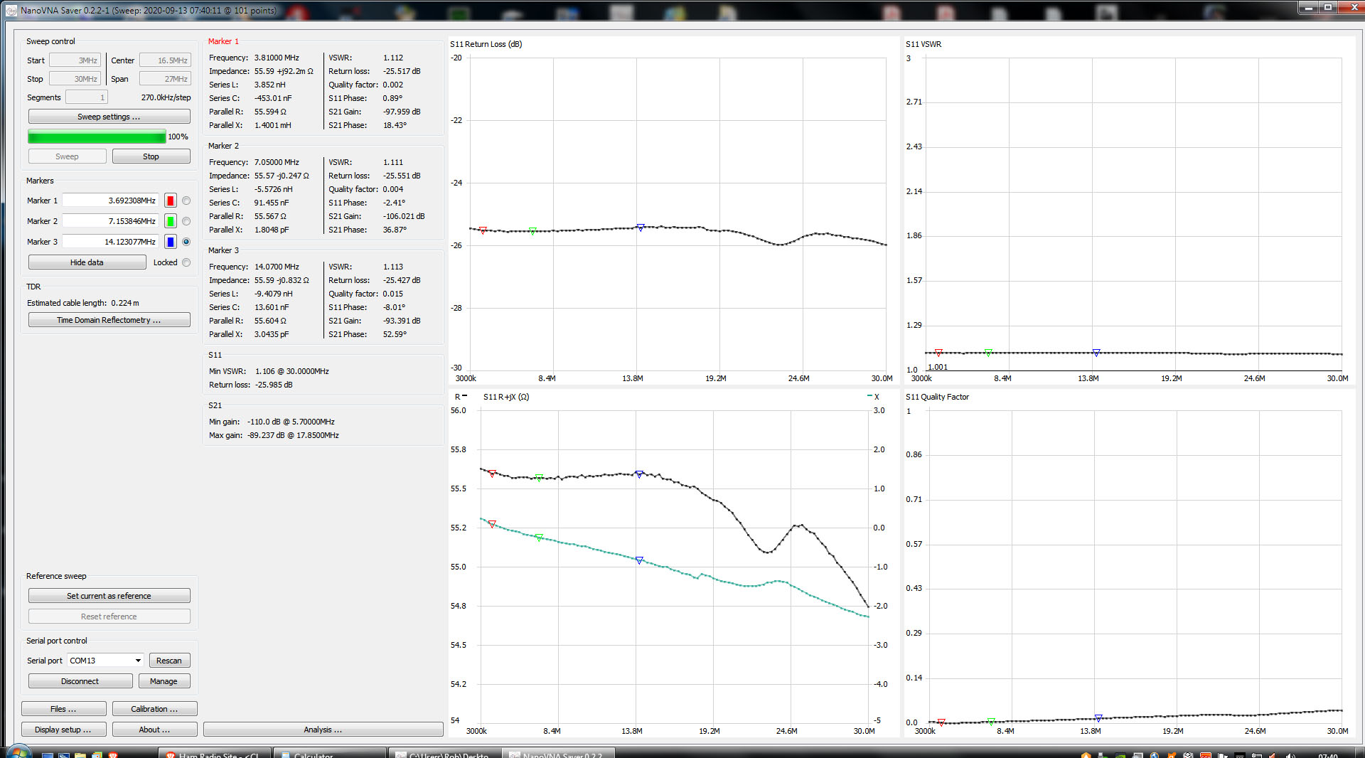
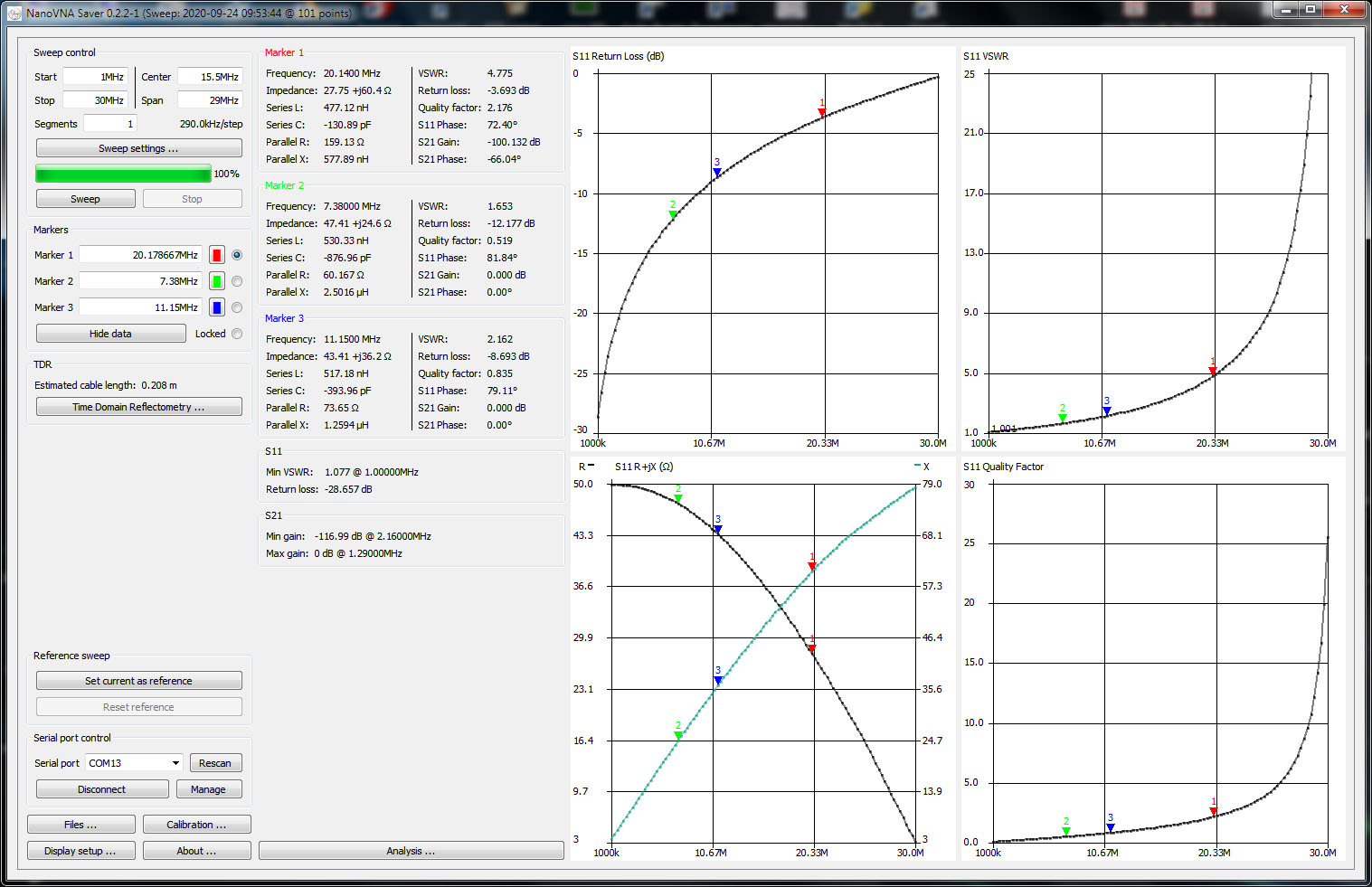
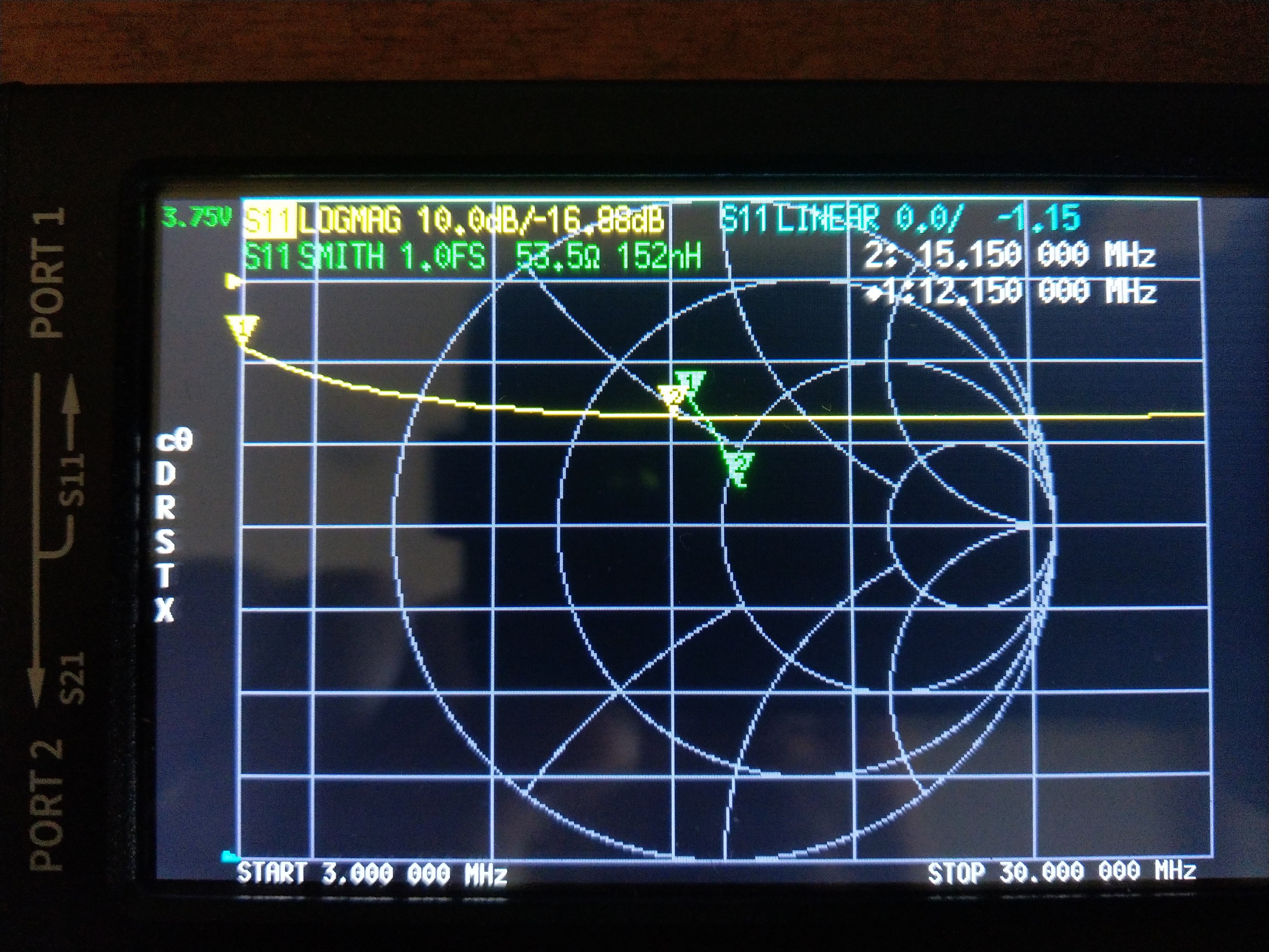
The following figures have been measured with an VNA
200 OHMS resistor on the load
3 MHZ 39.5 0.8J VSWR 1.26
7 MHZ 51.5 0.15J VSWR 1.03
14 MHZ 55.1 0.11J VSWR 1.102
The above figures show some reactive values, albeit very small but their presence indicates an unrated variable, this was expected due to the large bandwidth involved, but the return loss at 3 MHZ is exessive in my opinion .
The part the I cant reconcile is the large impedance dip at 3 MHZ, not sure why, is it the lack of turns or the external complex factors in the test I am conducting.
I welcome any comments please.
Note the VNA was calibrated...
The OCF antenna is an evolution of a Windom antenna, it differs in that its coax fed via a BALUN, all other operation principles are the same, the feed point is moved from the center point to give an impedance of 200 Ohms, thus the harmonics of the higher frequencies will give the same impedance, making the antenna a multi-band antenna, However the down side is that at the higher frequencies the propagation pattern will no longer be that of a dipole, with many lobes.
There is modelling on the web that shows this.
The first thing that struck me is that the quality of the BALUN is very important in obtaining a constant match to both the fundamental and the harmonics, ideally the matching component (BALUN) must have a flat response, this to provide the 4:1 transformation to 50 Ohms. BUT a big but, this point will exhibit a very reactive value that many show as 200 Ohms, none of the research I have done shows the complex value eg( 200 J-something) so the conclusion is that I am not going to spend time calculating this as there exists many unknowns that vary considerably with external factors, thus the assumption is that of 200 Ohms reactive, ( Here is why we have the common mode current issue. )
A transmission line or system, (I include the BALUN) at the feed point we expect to see that the voltage and current to be in phase, but a big BUT the point chosen is not going to give us a pure resistivity load, by the nature that its not at the center, its phase difference is going to be very different to a center fed dipole, take this a bit further and the resistivity value of the transmission line will only be so at the exit of the cable not at the connection to the dipole.
With an off center fed dipole this situation is worst, so it can be expected to have larger common mode currents, purely due to the reactive (J) values of the complex impedance.
Concluding, a very flat responding BALUN is a must to reduce and keep common mode currents to a minimum, but this is not easy to achieve.
I decided to construct a 4:1 BALUN dual core, here I would like some comments from those that may have already been down this road I am travelling on.
BALUN Construction:
Core T200-2 (Brown Colour) Happen to have these in my junk box
Construction is that of Common Mode Choke
8 turns total 4 by 4 opposite phase
Output in series, input in parallel
The following figures have been measured with an VNA
200 OHMS resistor on the load
3 MHZ 39.5 0.8J VSWR 1.26
7 MHZ 51.5 0.15J VSWR 1.03
14 MHZ 55.1 0.11J VSWR 1.102
The above figures show some reactive values, albeit very small but their presence indicates an unrated variable, this was expected due to the large bandwidth involved, but the return loss at 3 MHZ is exessive in my opinion .
The part the I cant reconcile is the large impedance dip at 3 MHZ, not sure why, is it the lack of turns or the external complex factors in the test I am conducting.
I welcome any comments please.
Note the VNA was calibrated...
")