CB radio Arduinoized.

VK3ZYZ

Moderator
Staff member
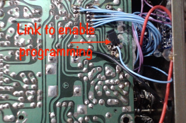
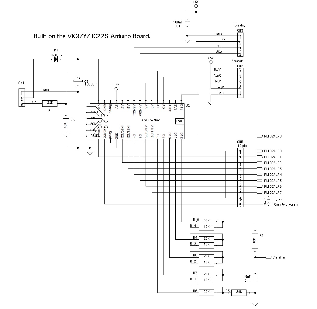
Here is the first try to mod a CB as per the IC22S.
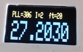
EDIT: This code now works in a test for the display. I am not looking at the PLL drive pins as yet, but it should be ok.
The encoder code is swapped from the IC22S code as a bigger PLL number is a lower frequency.
It should be easy to mod the code to suit other PLL configurations.
And if you want to see it, here is a short video of the display.

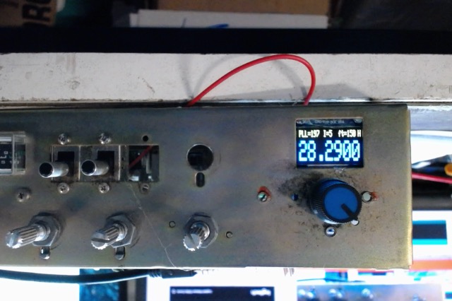
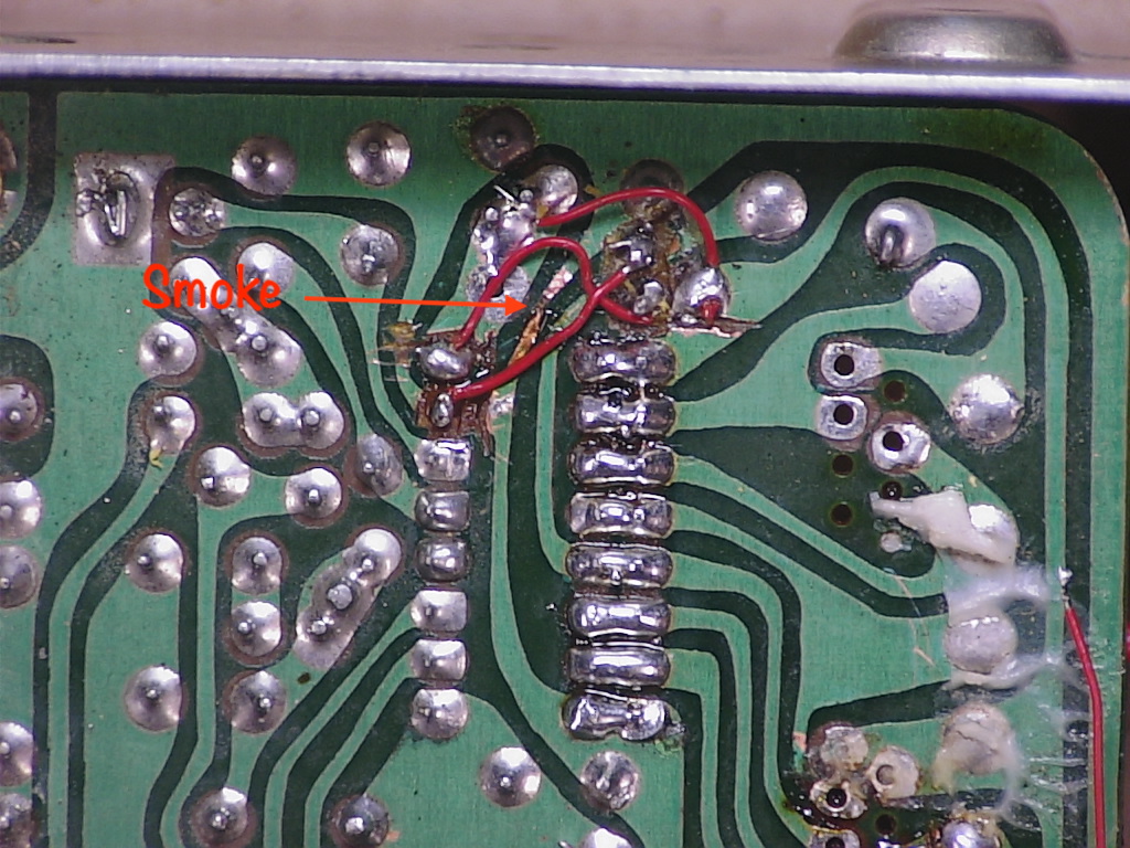
Next is to try it for real on a CB if I can find one suitable and working in my stash, then mod it to 28Mhz!
Also, add a PWM analog out to drive the clarifier input for tuning between channels. As it is, the steps are 10Khz, like the original CBs.
 

Attachments

Last edited:

VK3ZYZ

Moderator
Staff member
ArduinoCB_1Khz.jpg

Here is the display of a version that will drive the clarifier for finer tuning. That will need modding on the CB to make it work on TX as well as RX, and to increase the range if possible.

These is some debug code to write the top line info. PLL is the code written to the PLL02A chip, I is the fine tune index and ft is the fine tune value fetched from the table.
Also, the fine tune table is filled with pretend numbers. that will have to be worked out on test depending on the CB radio used.

int FineTune[] // find these values on test.
{ 0, 10, 20, 30, 40, 50, 60, 70, 80, 90,};


As will the PLL codes for that matter.

Arduino pins PD0-PD7 go to the corresponding PLL02A pins P0-P7,and pin 13 of the Arduino goes to P8 on the PLL02A
NOTE! on the Nano, TX is PD1 and RX is PD0 as shown below, so the board layout order is swapped for those 2 pins.
And, on your CB, some pins of the PLL02A will need to be isolated from the PCB as they are preset to +V or gnd.

1661229726938.png


Feel free to have a play.
 

Attachments

VK3ZYZ

Moderator
Staff member
ArduinoCB_OLED.jpg

In a Pearce Simpson Super Panther.
It fits well!
It is pity that the radio is not working as yet but it was a set I had to hand. It is missing a front and case.
PLL02A connections.jpg

As the code used the serial pins to drive the PLL02A, a link to disconnect the RXD pin from the radio allows programming.

This is still a work in progress!
 
Last edited:

VK3ZYZ

Moderator
Staff member
It has taken me a while but this is the closest to working version I have.
It tunes 1Khz steps using the clarifier. between 10Khz channels.
This is not calibrated as yet, or connected to the radio. The actual drive level and connection is still to be worked out. There may need to be radio mods to make it work.
Also, the values and direction of the voltage steps from the table, but that is just a matter of editing the table to suit.
The analog out steps currently are..

0.003V
0.253V
0.814V
1.378V
1.939V
2.746V
3.308V
3.871V
4.420V
4.670V

Port B bits PB1-PB4 (pins 10,11 & 12) form a 3 bit DAC using the R2R resistors.and the least significant bit, PB1, pin 9 is PWMed for fine steps.
So, it is capable of 256 * 8 steps resolution, or 2048 total steps.
I was hoping to use 4 bits switched R2R DAC and 1 bit PWM DAC but pin 8 does not PWM :(
So, pin PCo, pin 8 is just set low.
The PWM frequency, default set at around 400Hz was too low for good fast filtering so it is now 31Khz or so.
I have not implemented the TXin function, and it may not be needed for operation, but could be fun to do the display invert on TX if so desired.

Arduino CB.jpg
 

Attachments

VK3ZYZ

Moderator
Staff member
I have a puzzle to solve.
2 of the CBs have had a track blow when connected to my big power supply and the scope.
The Earth of the scope was clipped to the shield plate on the CB.
I thought I'd slipped and shorted something out for the first one.
BlownTrack.JPG


It is the gnd track under the PLL02A that feeds quite a bit of the PCB. Not a very good design as it is small.
My fear is the PLL02A chips may have died too but that is not known as yet.
So far I have not found out what the cause is but I suspect either a power supply fault or something in the other radio connected at the same time.
The PS does not have the 0V connected to gnd, but measures WRT mains earth, about -2V on the -Ve, and +10V on the +Ve. What current that can supply is what I need to test to see if it is a bit more that just leakage.

This is not a problem on my bench power supply and scope there, so I'll find a 12V lamp and hook it up to Earth and see what voltage reads then on the big supply. This may be gotcha that has been waiting for a while!
EDIT: I have not found the cause as yet. Coffee!!!!
 
Last edited:

VK3YNV

Administrator
Staff member
That's interesting. Looks like a short from power supply to ground through that board, anything outside the radio that might be causing it, like a shorted final transistor supplying volts to antenna ground?
 

BillC

Active member
My Electrophone CB. Was wired with a fuse blower zenner diode across the power input socket for polarity protection. The zenner went short all by itself one time and the fuse blew too. Had to replace both devices, no real hardship.
 

VK3ZYZ

Moderator
Staff member
I have tried to print a new front for the CBs as they are missing them.
3D_PrintedFront_1.jpg
3D_PrintedFront_2.jpg

But for some reason, my 3D printed fails after 5 hours into a 6 hour print :(
 
Last edited:
Top