V
VK2RK
Guest
Oven Controlled Crystal Oscillators can be sourced for as little as $5.00 and as much as $20.00 depending on type
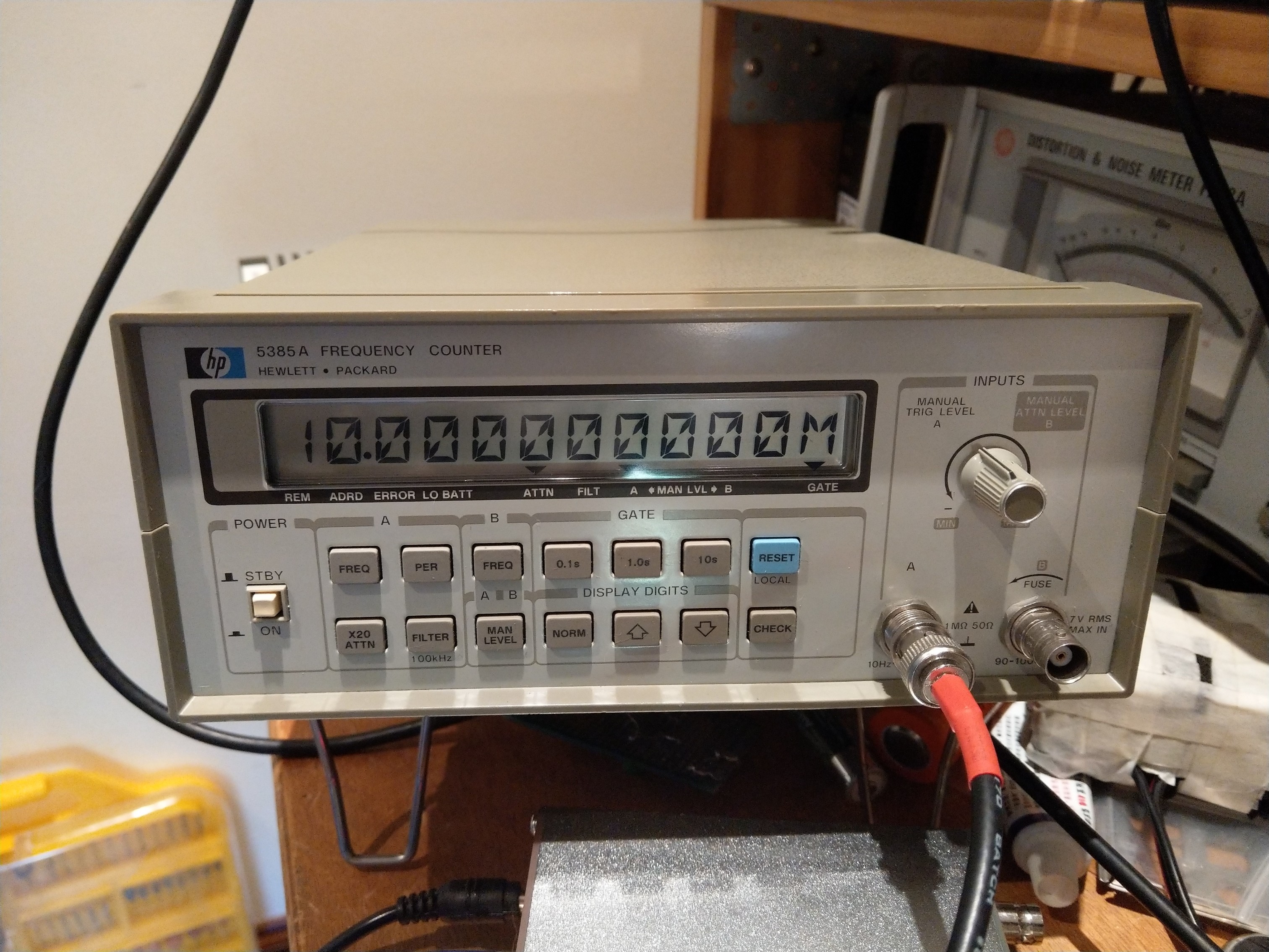
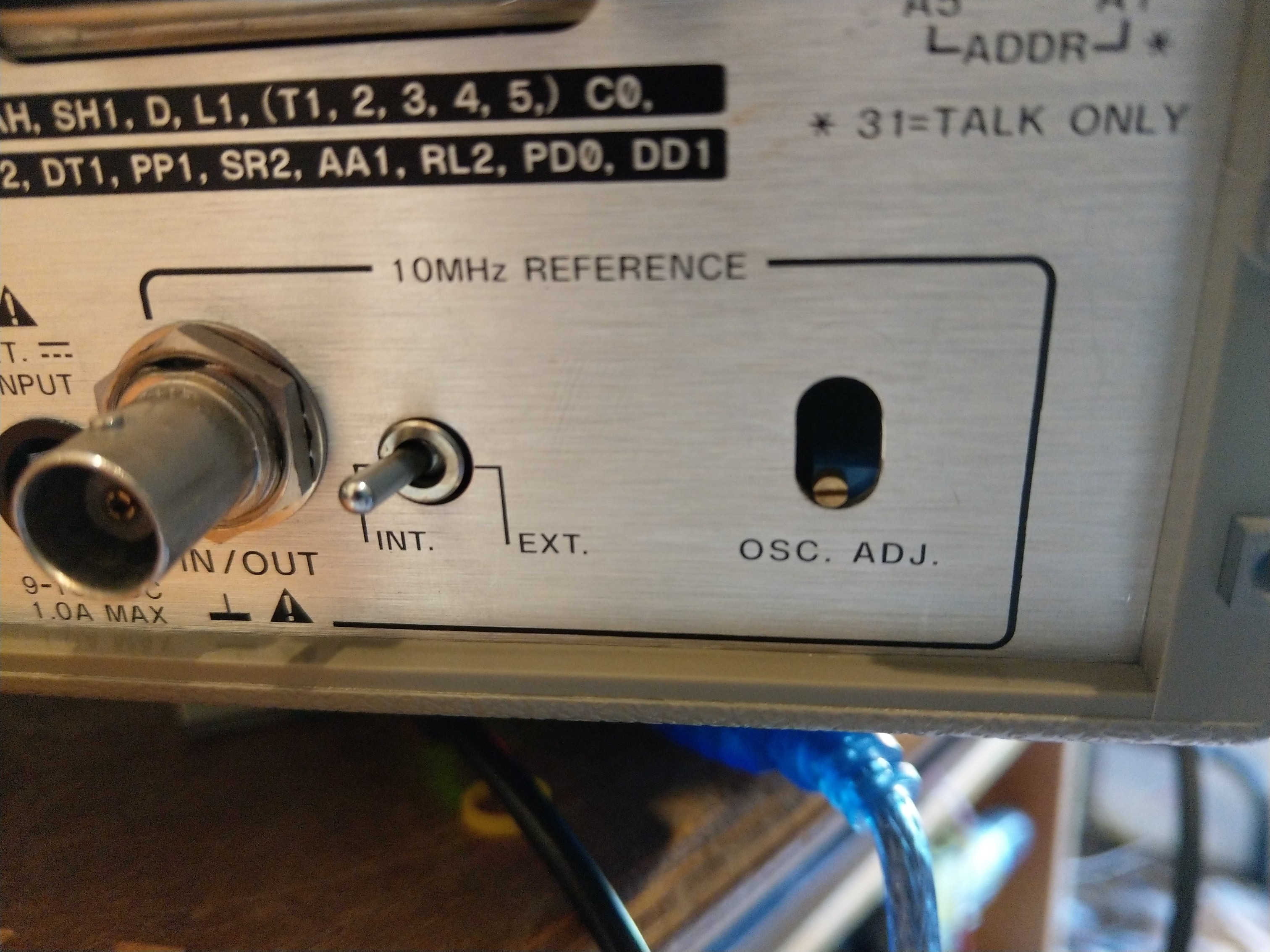
These units are surplus disposals, I think from the mobile phone industries, offering very good long term stability that for the price one should build one for the shack. Can be used as a reference signal at 10MHz to calibrate radios and measuring equipment, even as an external reference for instrument that use non ovenised oscillators that have poor short term stability.
These modules provide short term stability of +/- 5ppb (0.05Hz @10MHz) and long term stability of 100ppb per year equating to 1Hz @ 10MHz long term stability, this drift if the oscillator is run for one year continuously, the short term stability figure is the changes in the environment temperature with swings from -10 to 70 C. in reality the frequency inaccuracy will be a lot less the specified stated values.
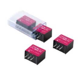
Modules used
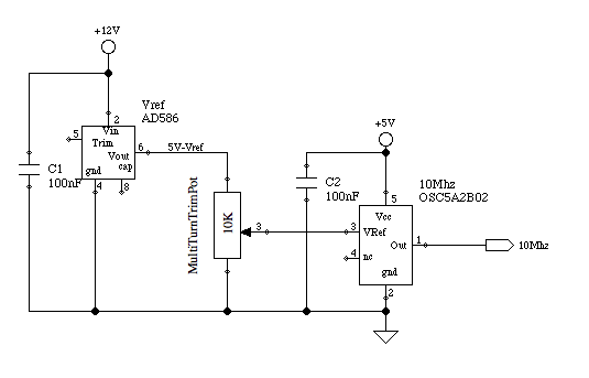
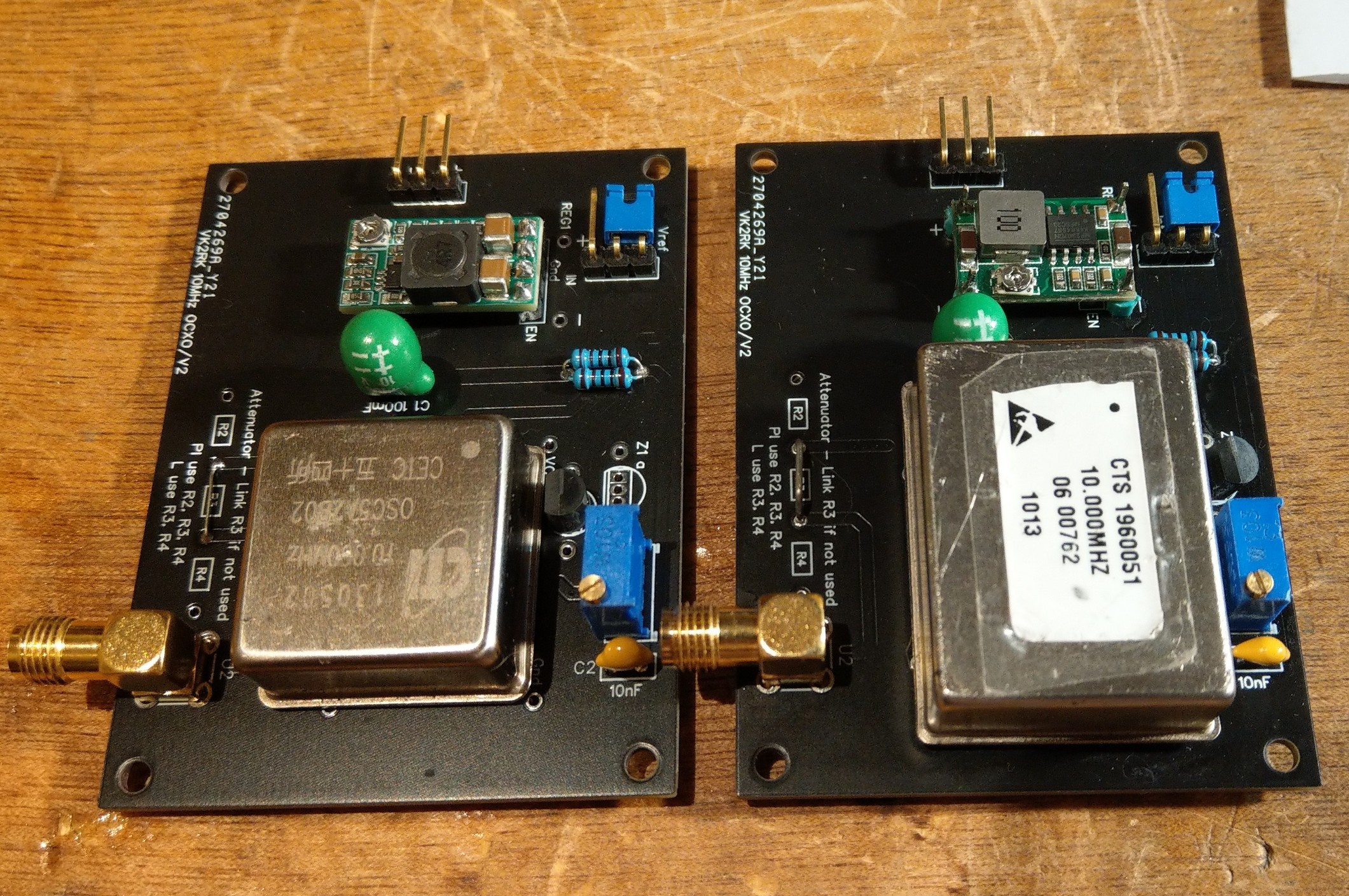
CTI OSC5A2B02 5Volts Square Wave Output (External voltage reference)
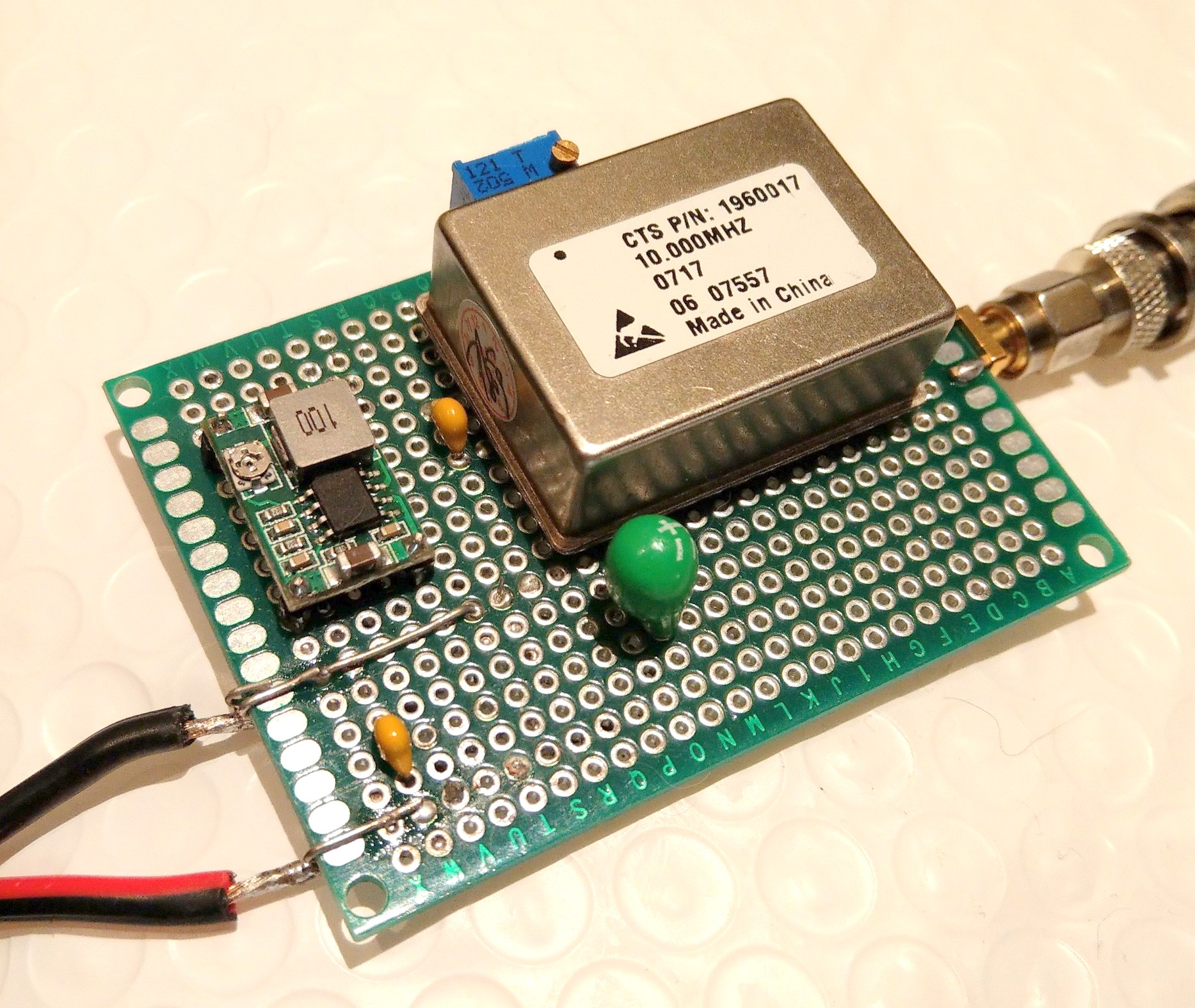
CTS 196 5Volts Sine wave output (Internal voltage reference)
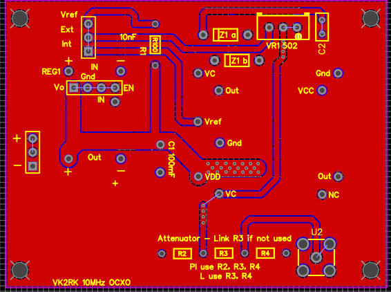
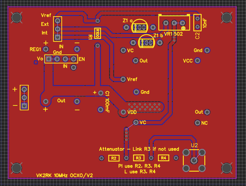
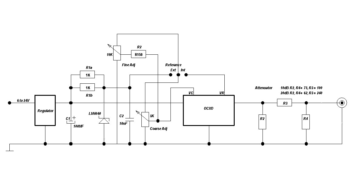
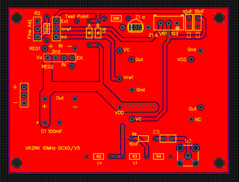
The design of the PCB is to accommodate either module, provision is made for required voltage reference components on the CTI module that are not fitted to the board if the CTS module is used.
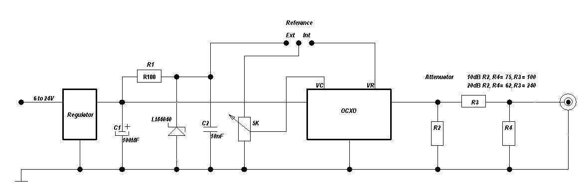
There is also on the PCB provision for a 50 Ohms to 50 Ohms attenuation is so required
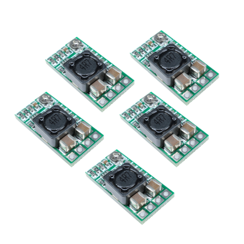
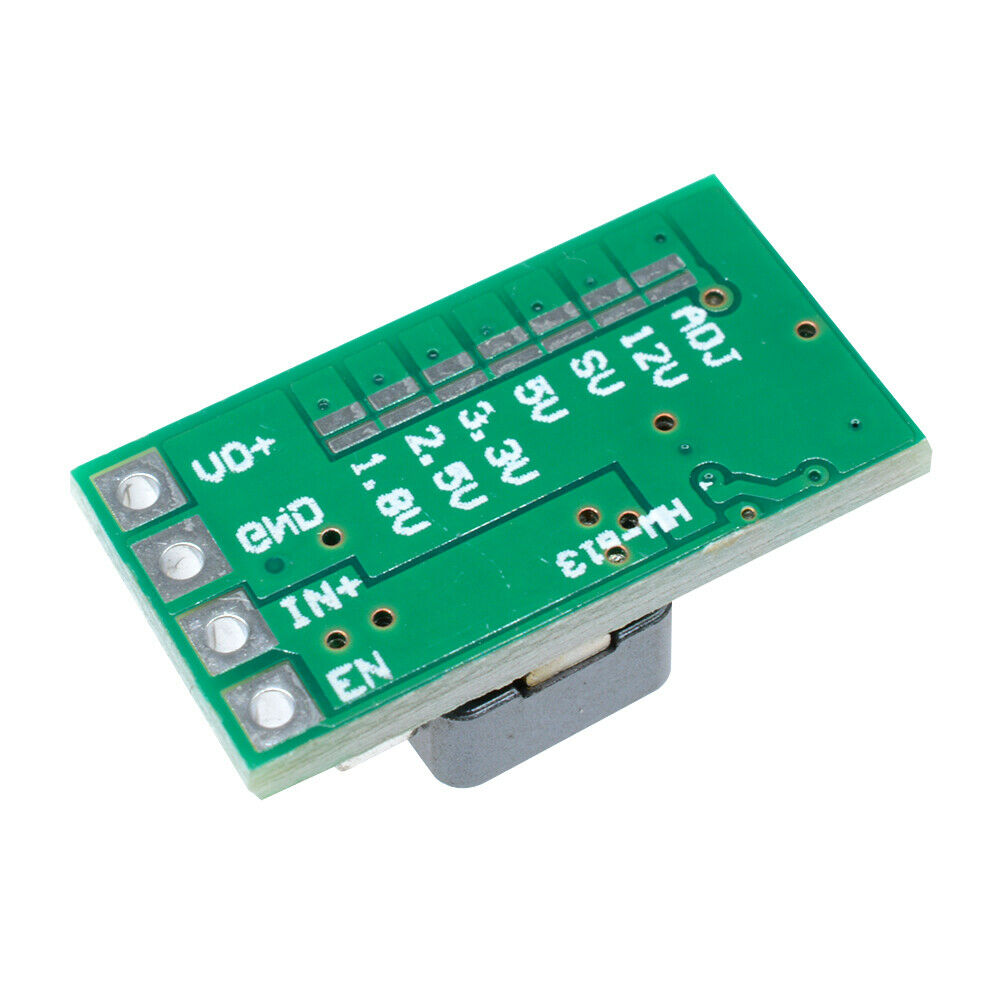
The operating voltage can accommodate from 6 volts to 24 volts, using a low cost buck regulator ($1.50)
Note that at voltages less that 13.8 V the input current will increase, its recommended to run the unit at 12 to 14.2 volts
The PCB is not yet ready for production as I am waiting for some components to confirm dimensions and to also provide for an alternate buck regulator, when I am happy with the PCB I will go into production.
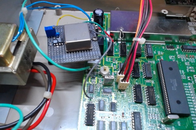
The prototype has been running now for several weeks and the stability is excellent exceeding specifications, the warm up time from first switch on is 3.5 minutes.
Note these modules new sell for many hundreds of dollars...
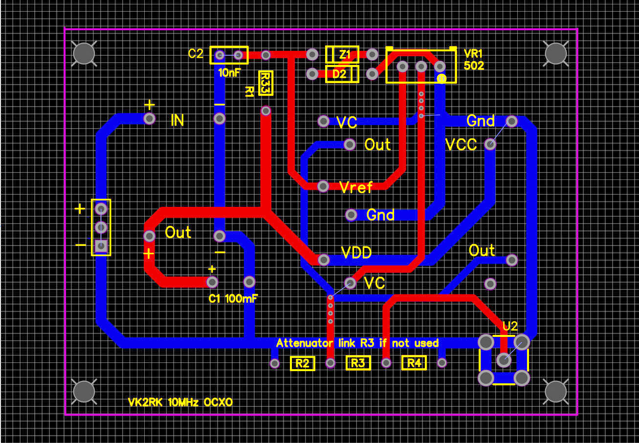
R1, Z1, D2, C2 Not required if using CTS Module (Reference Voltage Provision)
R2, R3, R4 Used to provide attenuation of output signal
These units are surplus disposals, I think from the mobile phone industries, offering very good long term stability that for the price one should build one for the shack. Can be used as a reference signal at 10MHz to calibrate radios and measuring equipment, even as an external reference for instrument that use non ovenised oscillators that have poor short term stability.
These modules provide short term stability of +/- 5ppb (0.05Hz @10MHz) and long term stability of 100ppb per year equating to 1Hz @ 10MHz long term stability, this drift if the oscillator is run for one year continuously, the short term stability figure is the changes in the environment temperature with swings from -10 to 70 C. in reality the frequency inaccuracy will be a lot less the specified stated values.
Modules used
CTI OSC5A2B02 5Volts Square Wave Output (External voltage reference)
CTS 196 5Volts Sine wave output (Internal voltage reference)
The design of the PCB is to accommodate either module, provision is made for required voltage reference components on the CTI module that are not fitted to the board if the CTS module is used.
There is also on the PCB provision for a 50 Ohms to 50 Ohms attenuation is so required
The operating voltage can accommodate from 6 volts to 24 volts, using a low cost buck regulator ($1.50)
Note that at voltages less that 13.8 V the input current will increase, its recommended to run the unit at 12 to 14.2 volts
The PCB is not yet ready for production as I am waiting for some components to confirm dimensions and to also provide for an alternate buck regulator, when I am happy with the PCB I will go into production.
The prototype has been running now for several weeks and the stability is excellent exceeding specifications, the warm up time from first switch on is 3.5 minutes.
Note these modules new sell for many hundreds of dollars...
R1, Z1, D2, C2 Not required if using CTS Module (Reference Voltage Provision)
R2, R3, R4 Used to provide attenuation of output signal
Last edited by a moderator: