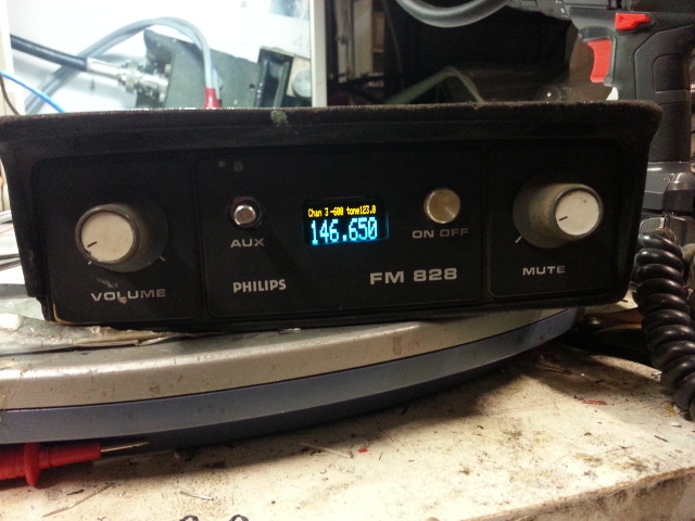
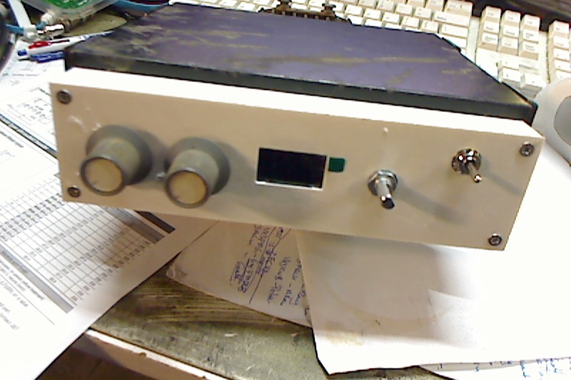
I have started on an FM828A.

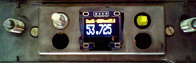
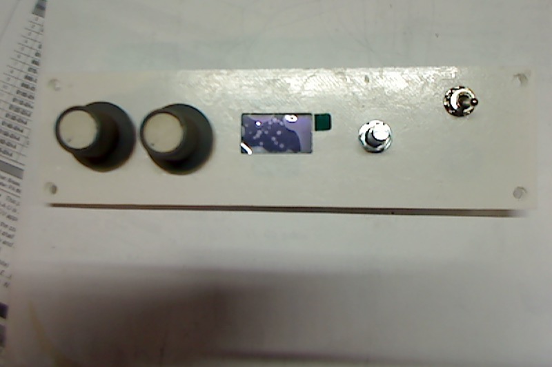
Front panel cut out to fit an OLED display.
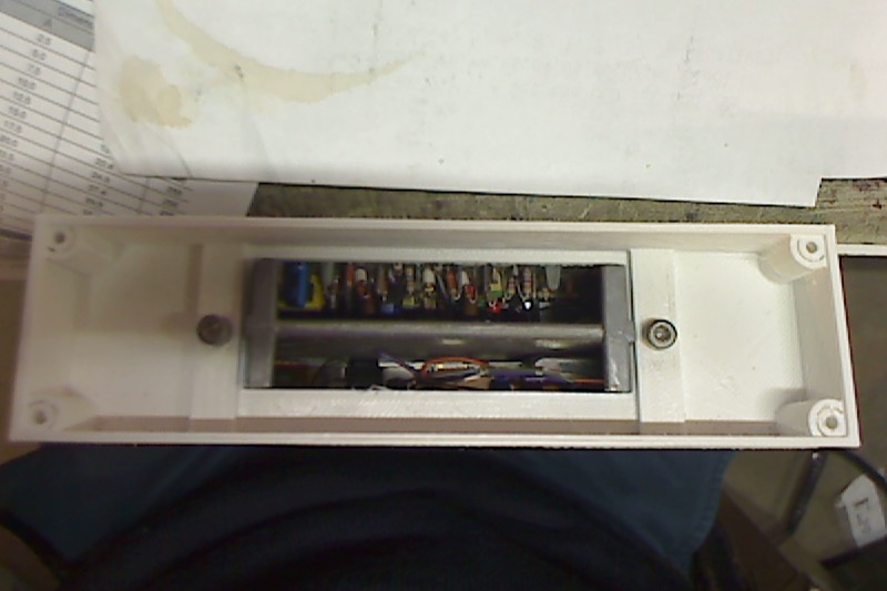
A slot needs to be filed into the chassis to fit the encoder.

And the power switch mount cut, removing the AUX switch. The 2 brown wires of the AUX are cut off, soldered together and insulated.

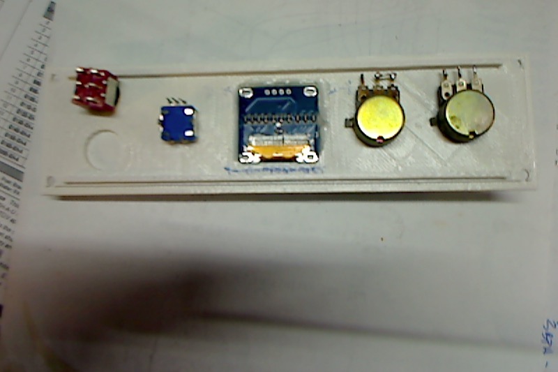
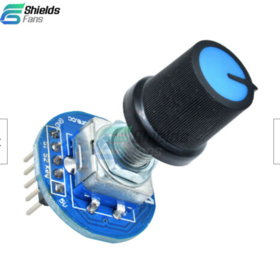
Then, the encoder is wired. I 3D printed a mounting bush.

It fits pretty well.


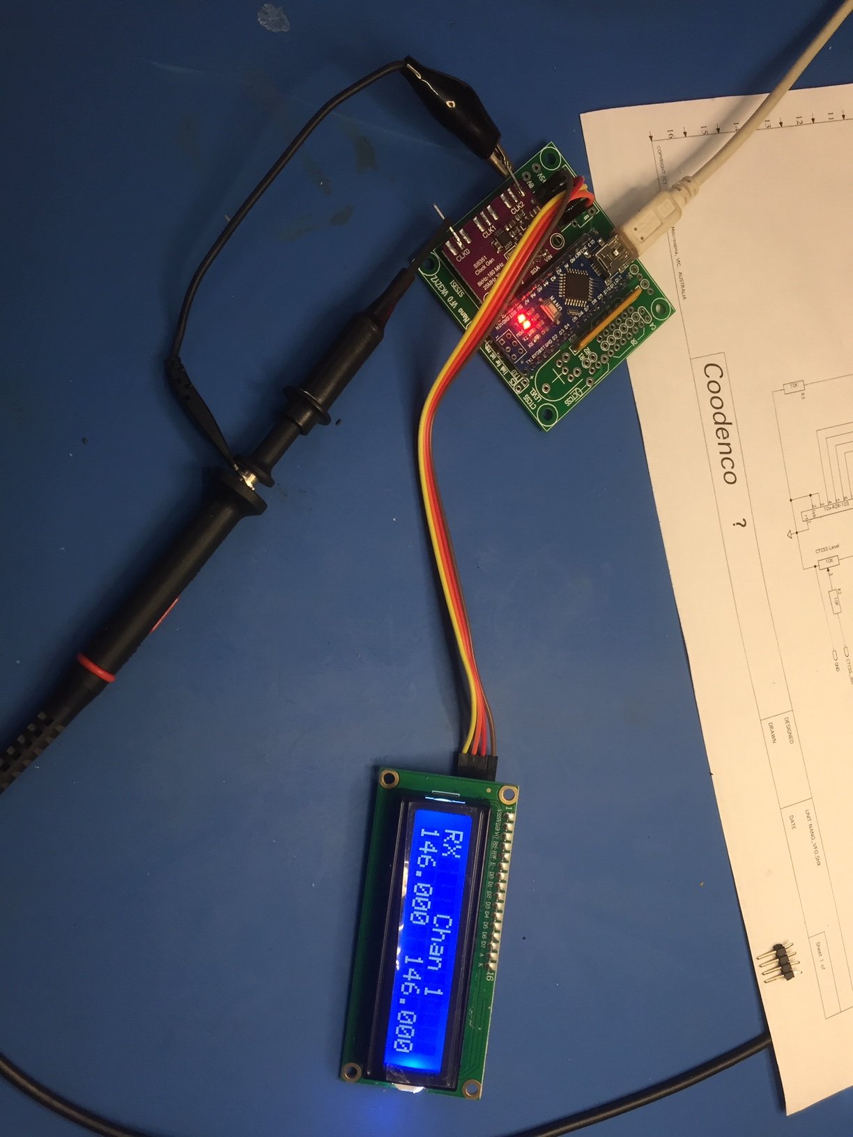
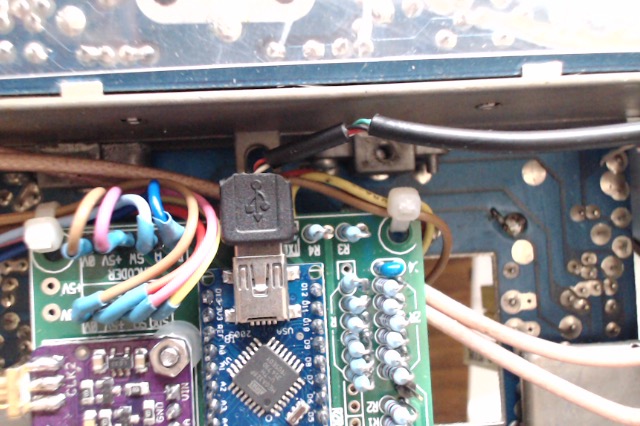
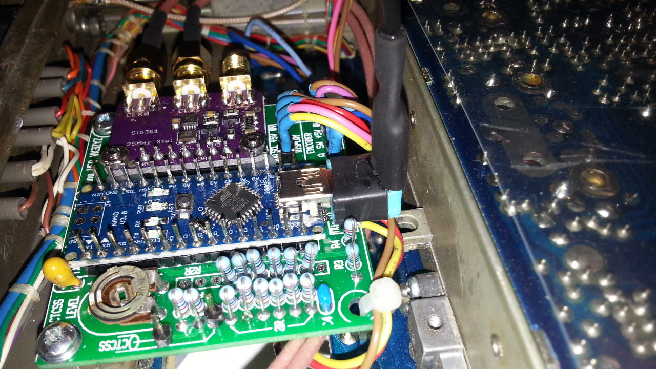
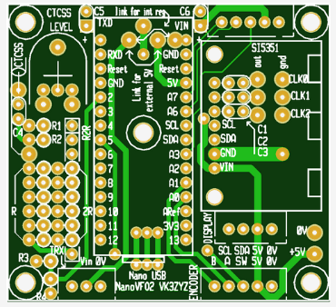
To mount the VFO board, it turns out there are a couple of holes just in the right place. A M/F M3 pillar for each. Make sure the thread is not too long to short the boards under. 2 nuts seem to be a good length.

And the board fits
")

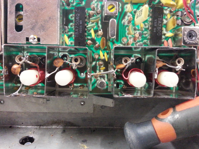
On the TX exciter board, remove the black wire..

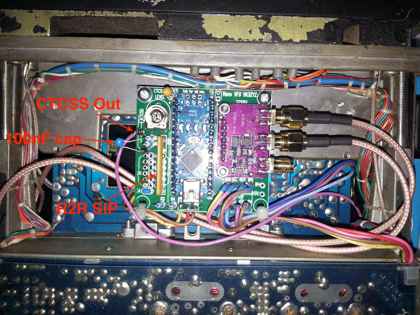
and add the VFO signal coax, with a coupling cap. Braid to 3 and cap from center to 41.

Similarly, on the RX, remove the black wire..

and add the coax as shown. there is a cap on board that can be used but the value may need increasing. Edit: I added a 150pF on the back of the PCB.

This is as far as I have got for now...

Something to eat sound good!
Edit:....
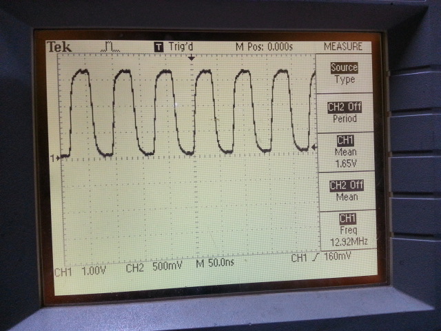
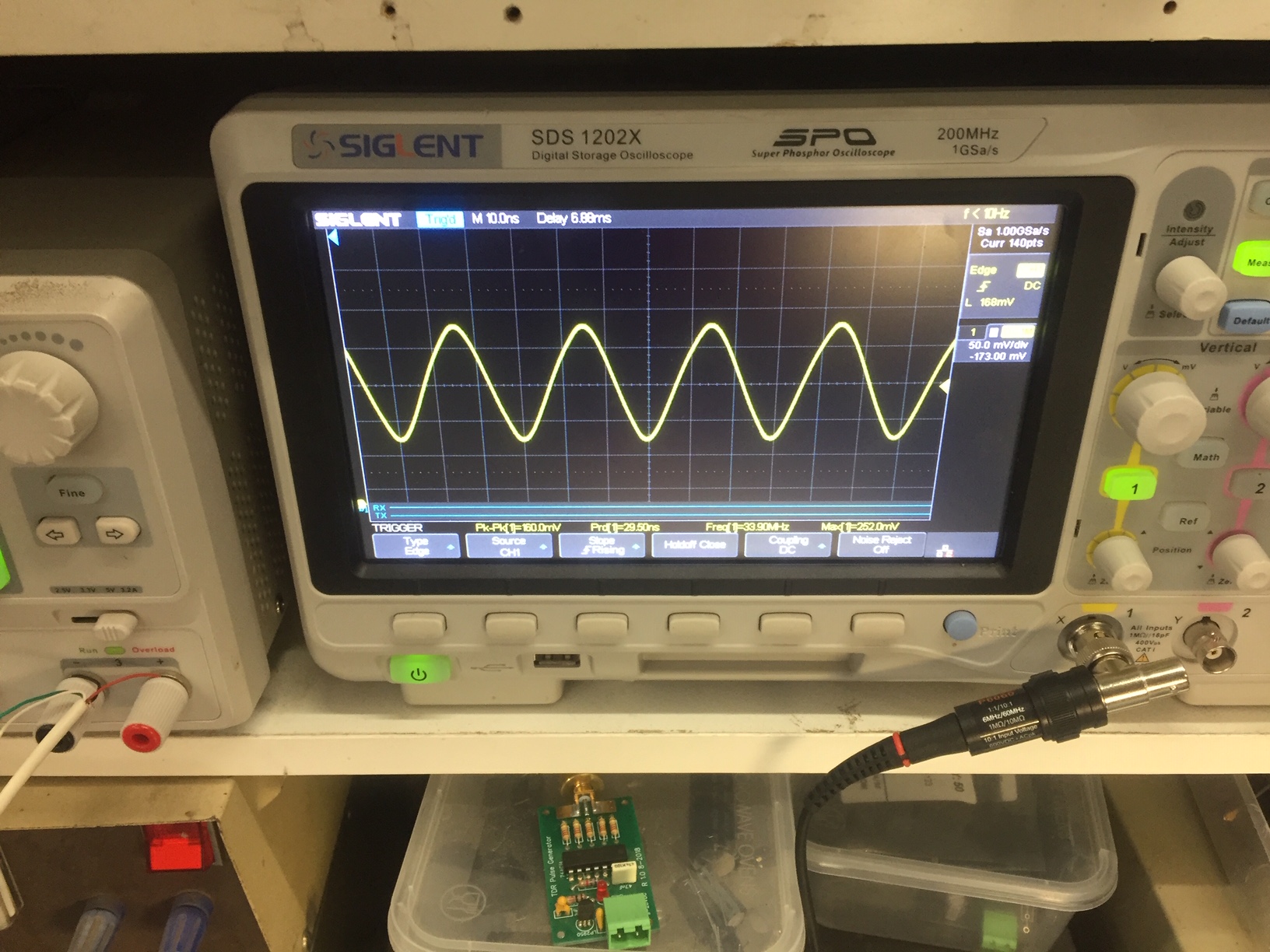
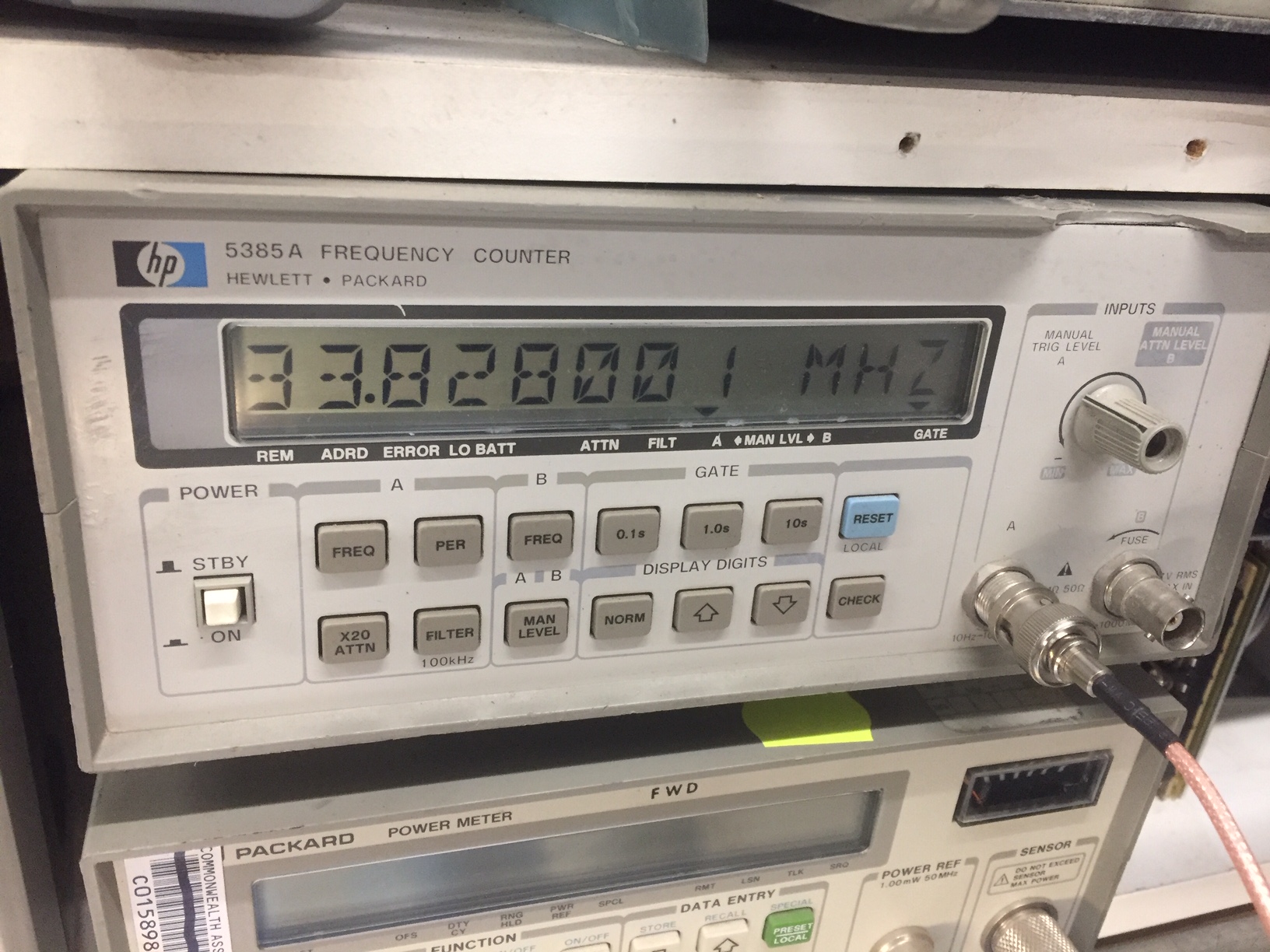
I am having problems with the code. It looks like a RX divisor of 3 is too low. It may be a maths problem or a limitation of the si5351.
A divisor of 6 looks ok.
And I need a knob for the encoder in the AUX position.
EDIT: The receiver tunes up ok, no mods needed. In fact I did it and listened to the club meeting on it.